Electrodeless discharge lamp apparatus and lighting fixture with the electrodeless discharge lamp apparatus

a technology of electrodeless discharge and lamp apparatus, which is applied in the direction of outdoor lighting, lighting and heating apparatus, fixed installation, etc., can solve the problems of reducing the proportion of heat conductor in the volume of the cavity, lowering the heat dissipation of the coupler, and difficult to transfer heat to the core and the heat conductor. , to achieve the effect of increasing the proportion of heat conductor, thin and uniform thickness of the bobbin, and reducing the proportion of the bobbin

Inactive Publication Date: 2009-06-11
IKEDA ELECTRIC CO LTD +1
View PDF10 Cites 1 Cited by
  • Summary
  • Abstract
  • Description
  • Claims
  • Application Information

AI Technical Summary

Benefits of technology

[0018]According to this structure, the bobbin can be separated in a radial direction of the induction coil. This makes it possible to separately mold the respective parts of the bobbin to be separated in the radial direction. Thus, it is not necessary to form, in the bobbin, a draft angle which has been necessary in the prior art when molding a tubular-shaped bobbin, and it is possible to make the thickness of the bobbin thin and uniform. In other words, the proportion of the bobbin in the volume of the cavity can be reduced to increase the proportion of the heat conductor, so that the heat dissipation of the coupler can be improved.
[0019]Further, by designing so that a cover portion placed between the winding start portion and the winding portion covers the winding start portion, it is possible to secure a sufficient creepage distance between the winding start portion and the winding portion. Thus, the insulation strength increases, making it possible to adapt to an increase in the starting voltage due to an increase in the output of the apparatus.
[0020]Further, by allowing an end of the hook-shaped cover portion to extend in a direction opposite to a winding direction of the induction coil, the winding start portion is hooked and held by the hook-shaped cover portion when winding the winding wire around the bobbin. This makes it possible to securely fix the induction coil to the bobbin, preventing a positional offset of the induction coil.
[0021]Further, placement of a portion of the heat conductor to substantially contact the induction coil not only makes it possible to dissipate, via the heat conductor, the heat from the core similarly as in the prior art, but also makes it easier to dissipate, via the heat conductor, the heat at a periphery of the induction coil which particularly increases in temperature.
[0022]Further, by designing so that a surface of the core in contact with the heat conductor is substantially flat, it is possible to maintain the dimensional accuracy of the contact surface of the core with the heat conductor even if the core is increased in size or length with the increase in the output of the apparatus, making it possible to obtain intimate contact between the core and the heat conductor. Thus, the heat from the core can be efficiently dissipated through the heat conductor.
[0023]Furthermore, provision of the electrodeless discharge lamp apparatus, which is superior in heat dissipation and enables an increase in the output of the apparatus, makes it possible to achieve an increase in light flux of a lighting fixture, so that the number of installations thereof can be reduced as compared to the prior art, making it possible to achieve a reduction in maintenance and a reduction in resource consumption.

Problems solved by technology

Since this causes the bobbin to increase in size radially, and since there is a limit in the diameter of the cavity, there has been a problem that the proportion of the heat conductor in the volume of the cavity decreases, consequently lowering the heat dissipation of the coupler.
Further, if a bobbin made of resin intervenes between an induction coil and a core so as to wrap the entire core therein such as in the case of using a tubular-shaped bobbin with no opening on a side surface thereof as in the electrodeless discharge lamp apparatus shown in patent document 1 (sic, correctly: the former document), then there is a problem that the heat generated from the induction coil or the periphery is blocked by the bobbin, making it difficult for the heat to be transferred to the core and the heat conductor, consequently lowering the heat dissipation of the coupler.
Particularly considering the increase in the output of the electrodeless discharge lamp apparatus, which is likely to cause concentration of plasma at the periphery of the induction coil and thus increase its temperature, there is a risk that mere dissipation of the heat from the core through the heat conductor as in the prior art may cause an undesirable increase in the temperature of the periphery of the induction coil and significant reduction in the light emission efficiency.
This causes inferior workability in manufacturing the apparatus as well as a cost disadvantage.
Furthermore, when the spatial distance between the winding start portion and the winding portion of the induction coil is maintained to secure insulation, it results in that the bobbin increases in size radially, and the proportion of the heat conductor in the volume of the cavity decreases, making it difficult to improve the heat dissipation of the coupler more effectively.

Method used


Image

  • Electrodeless discharge lamp apparatus and lighting fixture with the electrodeless discharge lamp apparatus
  • Electrodeless discharge lamp apparatus and lighting fixture with the electrodeless discharge lamp apparatus
  • Electrodeless discharge lamp apparatus and lighting fixture with the electrodeless discharge lamp apparatus

Examples


Embodiment Construction

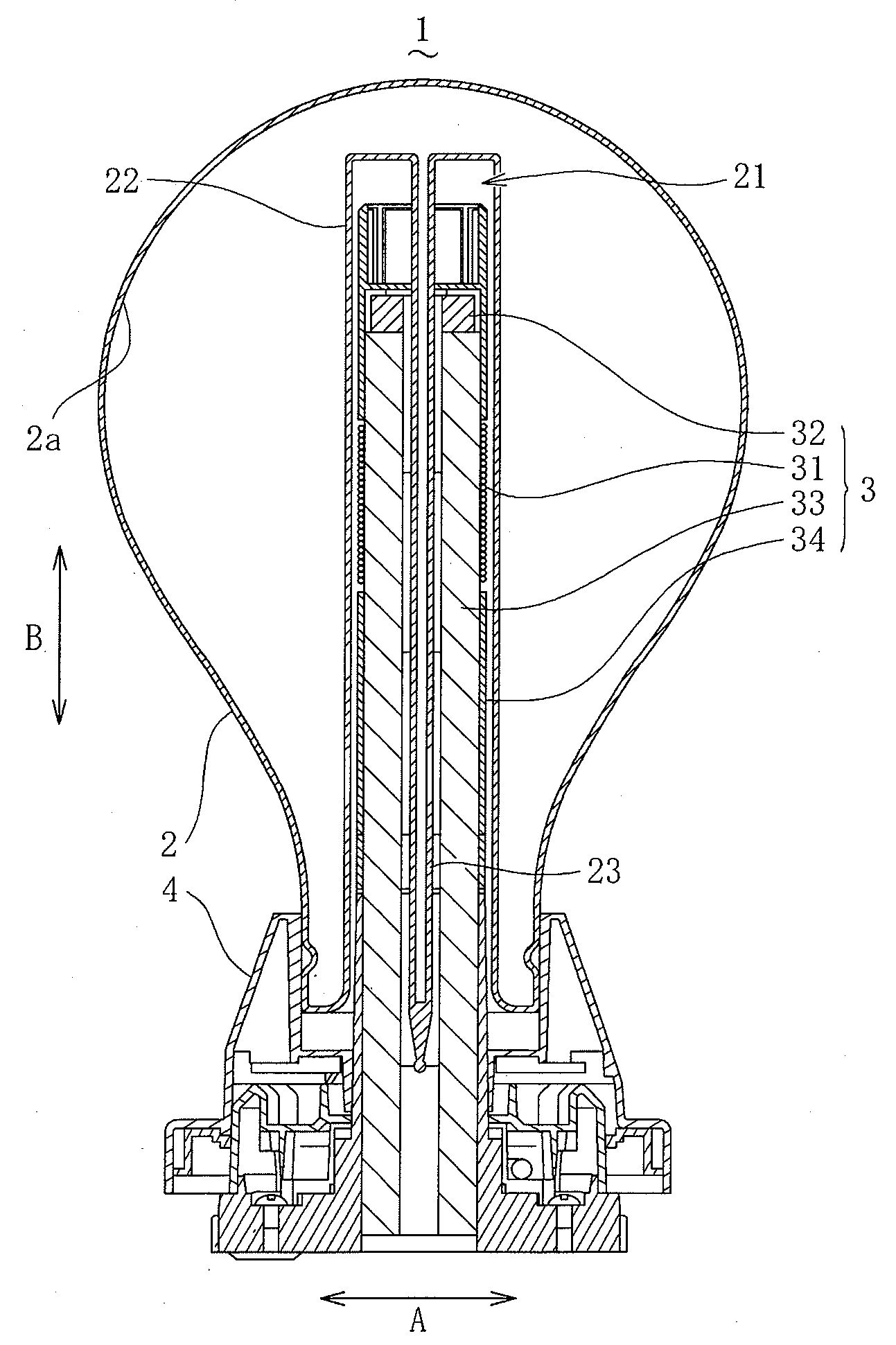
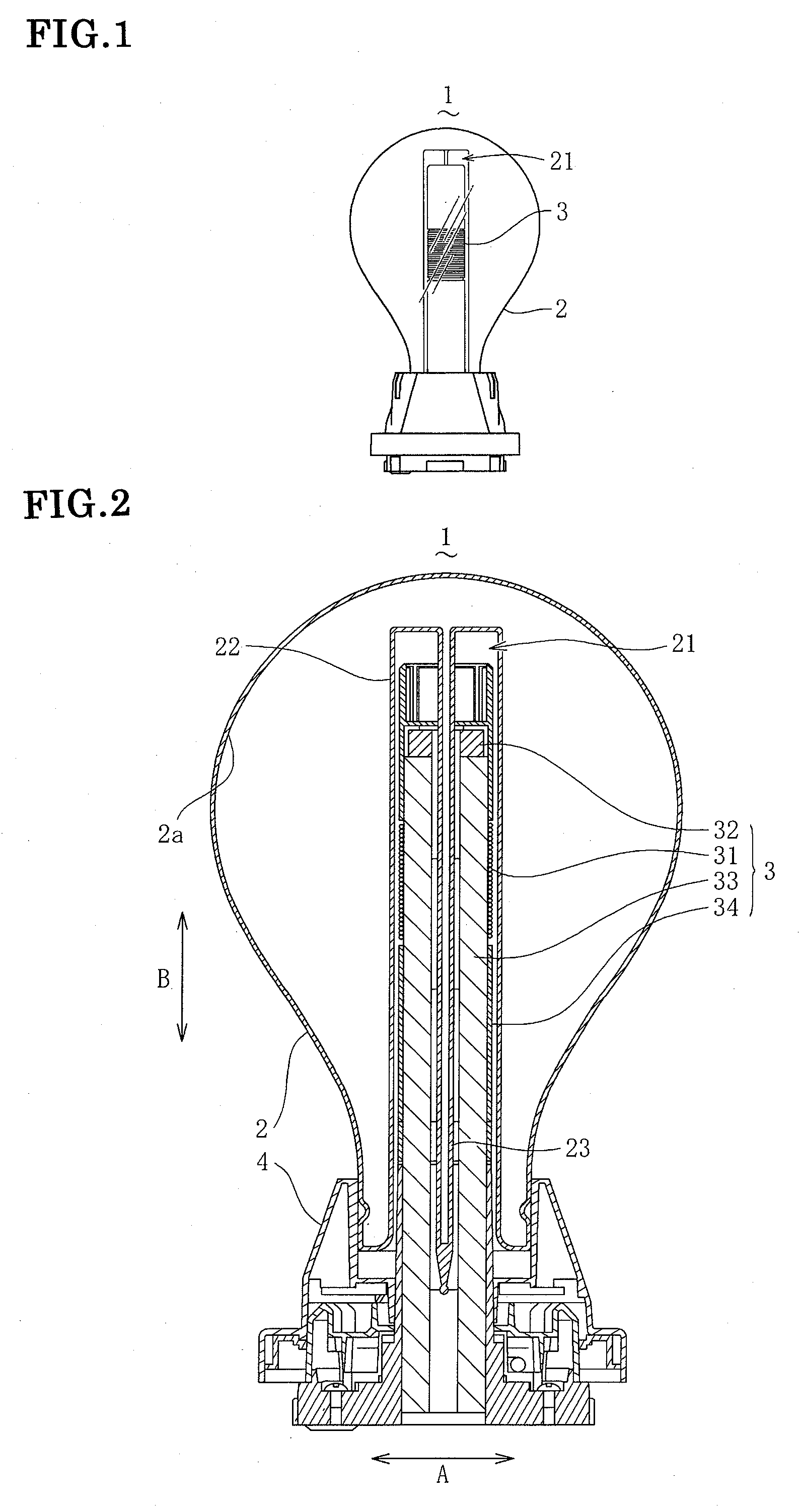
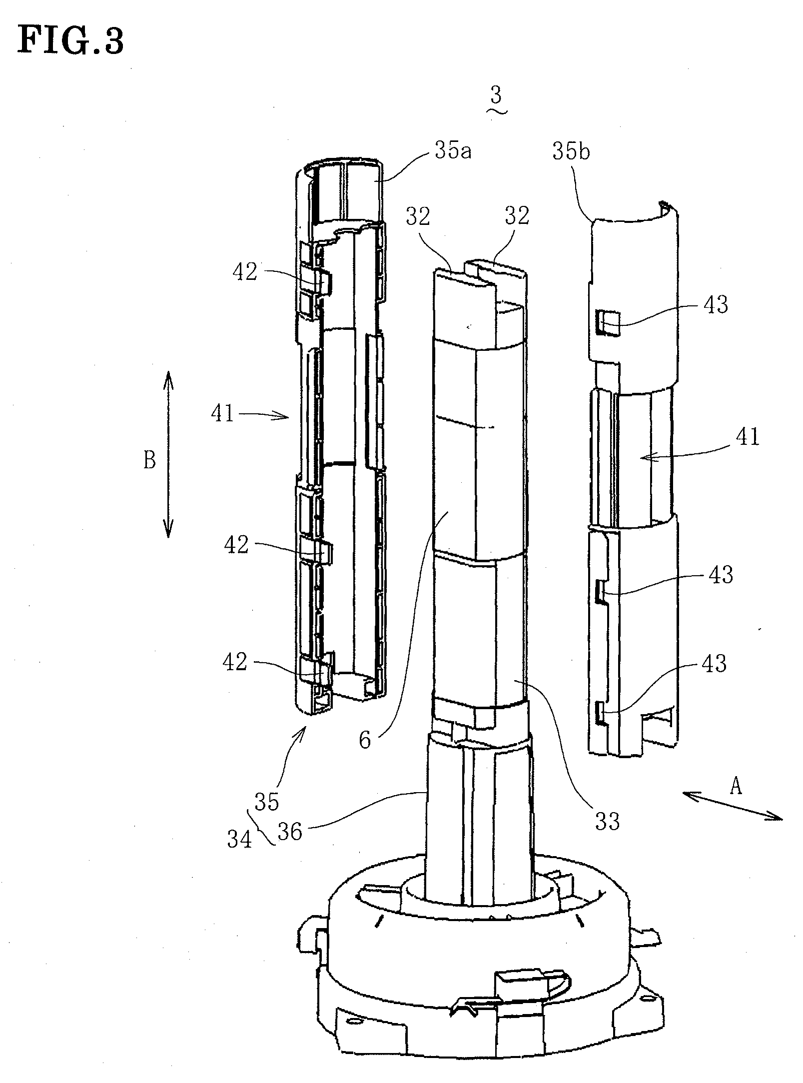
[0036]Hereinafter, an electrodeless discharge lamp apparatus according to an embodiment of the present invention will be described with reference to the drawings. As shown in FIG. 1, an electrodeless discharge lamp apparatus 1 comprises a light-transmitting bulb 2 containing a discharge gas and a coupler (high frequency electromagnetic field generator) separably accommodated in a cavity 21 formed in the bulb 2 for generating a high frequency electromagnetic field.

[0037]As shown in FIG. 2, the bulb 2 is formed in a substantially spherical shape, and has provided therein a stem 22 forming a cavity 21 extending to the inner center thereof. Further, the bulb 2 has a gas outlet tube 23 provided in the cavity 21. The gas outlet tube 23 is used to exhaust air in the bulb 2, and fill a discharge gas such as mercury in the bulb 2, while its tube end is closed after the gas filling. Besides, a fluorescent material is coated on an inner surface 2a of the bulb 2. The bulb 2 emits light when ult...


PUM


Abstract

An electrodeless discharge lamp apparatus is provided which is increased in heat dissipation, making it possible to adapt to an increase in output of the apparatus. The electrodeless discharge lamp apparatus comprises a bulb containing a discharge gas and a coupler accommodated in a cavity formed in the bulb for generating a high frequency electromagnetic field. The coupler has: an induction coil; a core inserted into the coil; a heat conductor for conducting heat generated from the coil and the core; and a bobbin made of resin which accommodates the core and the heat conductor therein, and which has the coil wound therearound. The bobbin is designed to be separated in a radial direction of the coil, so that it is possible to separately mold the respective parts of the bobbin. Thus, it is not necessary to form, in the bobbin, a draft angle which has been necessary in the prior art when molding a tubular-shaped bobbin, and it is possible to make the thickness of the bobbin thin and uniform, so that the proportion of the bobbin in the volume of the cavity can be reduced to increase the proportion of the heat conductor.

Description

TECHNICAL FIELD[0001]The present invention relates to an electrodeless discharge lamp apparatus in which a discharge gas filled in a bulb is excited by a high frequency electromagnetic field to emit light, and to a lighting fixture with the electrodeless discharge lamp apparatus.BACKGROUND ART[0002]As shown in Published Japanese Translation of PCT Application Hei 11-501152 or the pamphlet of International Patent Publication WO 05 / 041245, a known electrodeless discharge lamp apparatus of this kind is the apparatus with the so-called internal winding method, which comprises a light-transmitting bulb containing a discharge gas and a high frequency electromagnetic field generator (hereafter referred to as coupler) accommodated in a cavity formed in the bulb for generating a high frequency electromagnetic field. In such apparatus, the coupler comprises: an induction coil through which a current flows to generate a high frequency electromagnetic field; a core formed of a soft magnetic mat...

Claims


Application Information

Patent Timeline
Patent Type & Authority Applications(United States)
IPC IPC(8): H01J61/02F21S2/00F21V29/00F21Y101/00H01J65/04
CPCF21S8/08H01J65/048F21W2131/103
Inventor OGASAWARA, HIROSHIMIYASAKI, HIROSHIKAKEHASHI, HIDENORIHARADA, KEISUKESHIBATA, YOSHINOBU
Owner IKEDA ELECTRIC CO LTD
Why Eureka
Try Eureka