Pseudo-differential output driver with high immunity to noise and jitter

a differential driver and high-immunity technology, applied in logic circuits, pulse techniques, reliability increasing modifications, etc., can solve the problems of large area consumption, noise and jitter, differential drivers are often relatively complex, etc., and achieve the effect of greater immunity to noise and jitter

Active Publication Date: 2006-11-30
MICRON TECH INC
View PDF52 Cites 37 Cited by
  • Summary
  • Abstract
  • Description
  • Claims
  • Application Information

AI Technical Summary

Benefits of technology

[0007] In another embodiment of the invention, the pseudo-differential output is preferably also coupled to VSS through the above programmable impedance and ODT circuitry. The output is also preferably coupled to VCC through another programmable impedance and ODT circuitry. These programmable circuitries can further adjust the voltage swing of

Problems solved by technology

However, they are quite susceptible to noise and jitter, such as that caused by unregulated power supply voltages.
However, differential drivers a

Method used


Image

  • Pseudo-differential output driver with high immunity to noise and jitter
  • Pseudo-differential output driver with high immunity to noise and jitter
  • Pseudo-differential output driver with high immunity to noise and jitter

Examples


Embodiment Construction

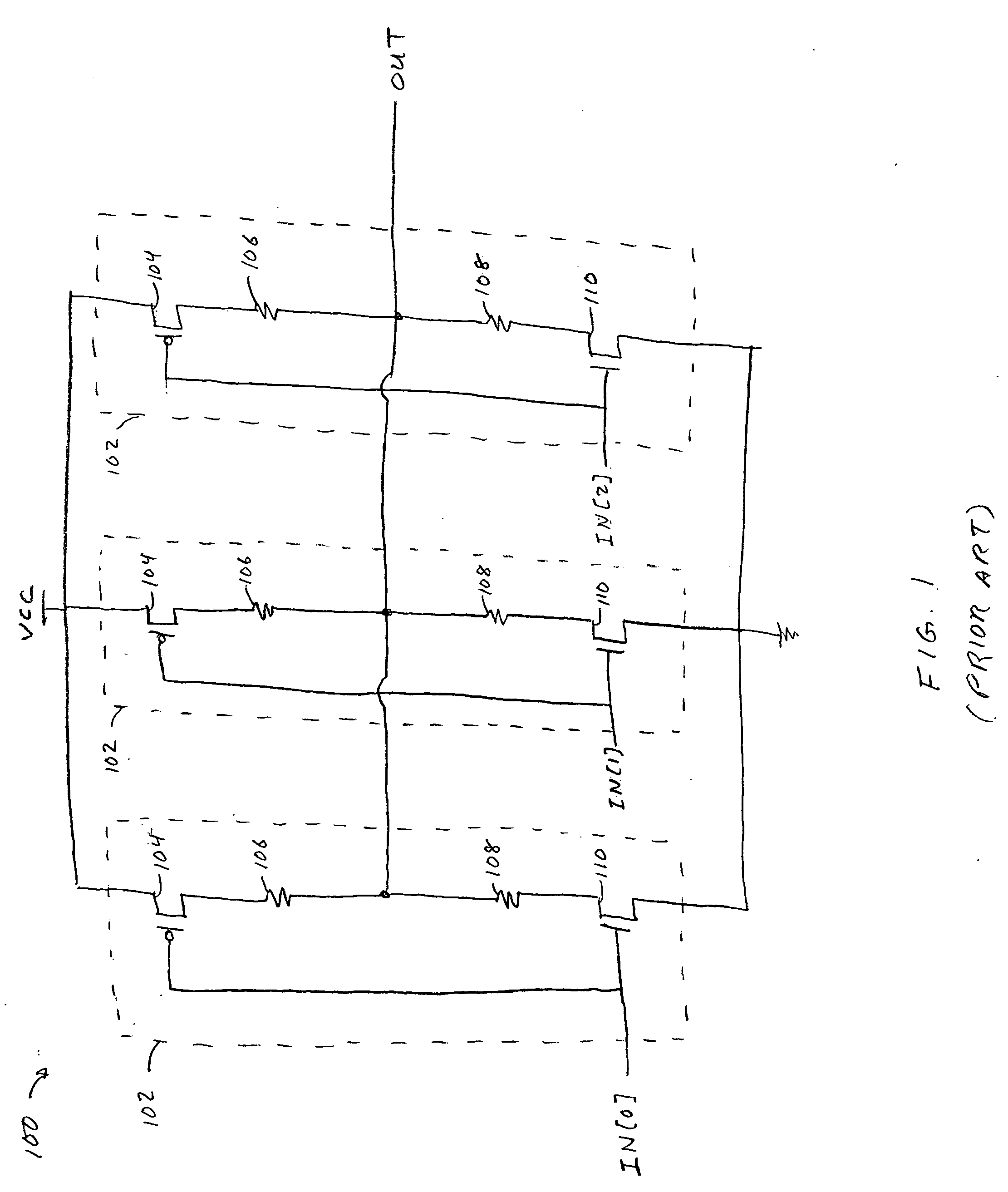
[0015]FIG. 1 illustrates a known single-ended output driver 100. Single-ended output driver 100 includes driver blocks 102 coupled in parallel between a source of relatively high voltage (“VCC”) and a source of relatively low voltage (“VSS”). Each driver block 102 includes P-type metal-oxide semiconductor (“PMOS”) transistor 104, resistors 106 and 108, and N-type metal-oxide semiconductor (“NMOS”) transistor 110, all serially coupled between VCC and VSS. Although single-ended output driver 100 includes three driver blocks 102, any suitable number of driver blocks 102 can be used.

[0016] Each driver block 102 accepts a single bit IN[N] of input signal bus IN, which is coupled to the gates of PMOS transistor 104 and NMOS transistor 110, and drives output signal OUT, which is coupled between resistors 106 and 108. Each driver block 102 behaves substantially like an inverter without a full rail-to-rail voltage swing. That is, when its input signal IN[N] represents a logical 0, PMOS tran...


PUM


Abstract

Circuits and methods are provided for transmitting a pseudo-differential output signal with relatively high immunity to noise and jitter. The output driver of the invention receives two differential input signals and outputs a single output signal with low voltage transistors and programmable impedance and on-die termination circuits. The pseudo-differential output driver consumes little circuit area and has low output capacitance.

Description

BACKGROUND OF THE INVENTION [0001] This invention relates to an integrated circuit driver. More particularly, this invention relates to a pseudo-differential output driver. [0002] Drivers are common circuits used for transmission of signals, either between integrated circuits (“ICs”) or within a single IC. For instance, driver circuitry can be used to transmit (1) data to and from a memory or (2) control signals to and from a memory controller. There are many types of drivers, each with their own advantages and disadvantages. [0003] One type is a “single-ended” output driver, which receives an input signal and generates an output signal. Information is typically conveyed by the voltage of the output signal, which is substantially equal to either a relatively high voltage, such as that of a power supply (“VCC”), or a relatively low voltage, such as that of ground (“VSS”). Single-ended drivers are relatively simple, consume relatively little area, require a relatively low pin count, a...

Claims


Application Information

Patent Timeline
IPC IPC(8): H03K19/094
CPCH03K19/018585H03K19/018521
Inventor KING, GREG
Owner MICRON TECH INC
Why Eureka
Try Eureka