
Tera-hertz wave transmitting optical component, tera-hertz wave optical system, tera-hertz band wave processing device and method

a technology of terahertz wave and transmitting optical components, which is applied in the direction of optical elements, polarising elements, instruments, etc., can solve the problems of inability to accurately replace the terahertz light source in the same position as the pinhole in patent reference 1, and difficulty in handling invisible ligh

Inactive Publication Date: 2006-11-30
RIKEN +1
View PDF4 Cites 23 Cited by
  • Summary
  • Abstract
  • Description
  • Claims
  • Application Information

AI Technical Summary

Benefits of technology

[0029] A terahertz band wave processing method of the present invention is configured to have a detector position adjustment step of adjusting a direction and a position of a detector for detecting predetermined terahertz waves to a traveling direction of said terahertz waves, an aperture setting step of setting at least one aperture in a position in which a measured value of the detector does not decrease, and a pilot optical axis adjustment step of passing predetermined pilot light through the aperture using a pilot light guide mirror and coaxially superimposing the optical axis of said pilot light on the optical axis of the terahertz waves, and is characterized in that predetermined visible light is used as pilot light and the optical axis of said visible light is superimposed on the optical axis of the terahertz waves and the optical axis of said terahertz waves can be visually recognized in a simulated manner by the visible light.
[0031] Whereas cycloolefin was conventionally used as material of an optical system component, the present inventors found that said component had good transmission characteristics with respect to terahertz waves as a result of more specifically examining characteristics of the optical component made of cycloolefin.

Problems solved by technology

Also, the terahertz band is invisible light and has a problem that handling of the invisible light is difficult as compared with visible light.
Also, in the conventional arts disclosed, it is very difficult to accurately replace the terahertz light source in the same position as that of the pinhole in Patent Reference 1.
As a result of this, by only replacing the pinhole with the terahertz light source after alignment of the terahertz optical system is adjusted with reference to the transmitted light of the pinhole, its alignment cannot be adjusted accurately.
As a result of this, a problem of taking vast amounts of time and effort is involved.
In the art of Patent Reference 2, it is necessary to use superconducting material and the art has problems that cost is high and also production is difficult.
The art of Patent Reference 3 has a problem that its production is complicated.
However, this art has a problem of requiring a large-scale measurement system.

Method used


Image

  • Tera-hertz wave transmitting optical component, tera-hertz wave optical system, tera-hertz band wave processing device and method
  • Tera-hertz wave transmitting optical component, tera-hertz wave optical system, tera-hertz band wave processing device and method
  • Tera-hertz wave transmitting optical component, tera-hertz wave optical system, tera-hertz band wave processing device and method

Examples


Embodiment Construction

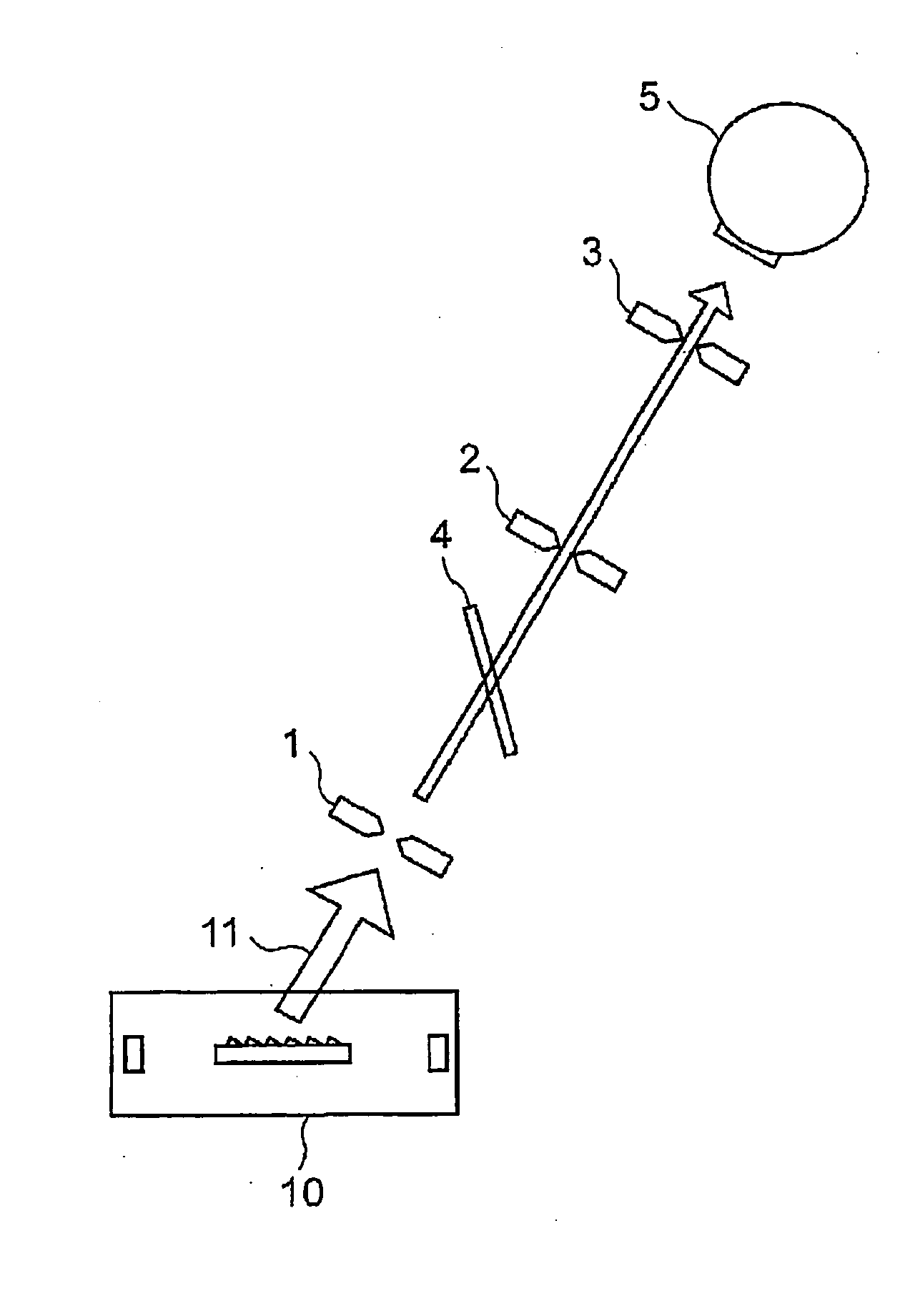
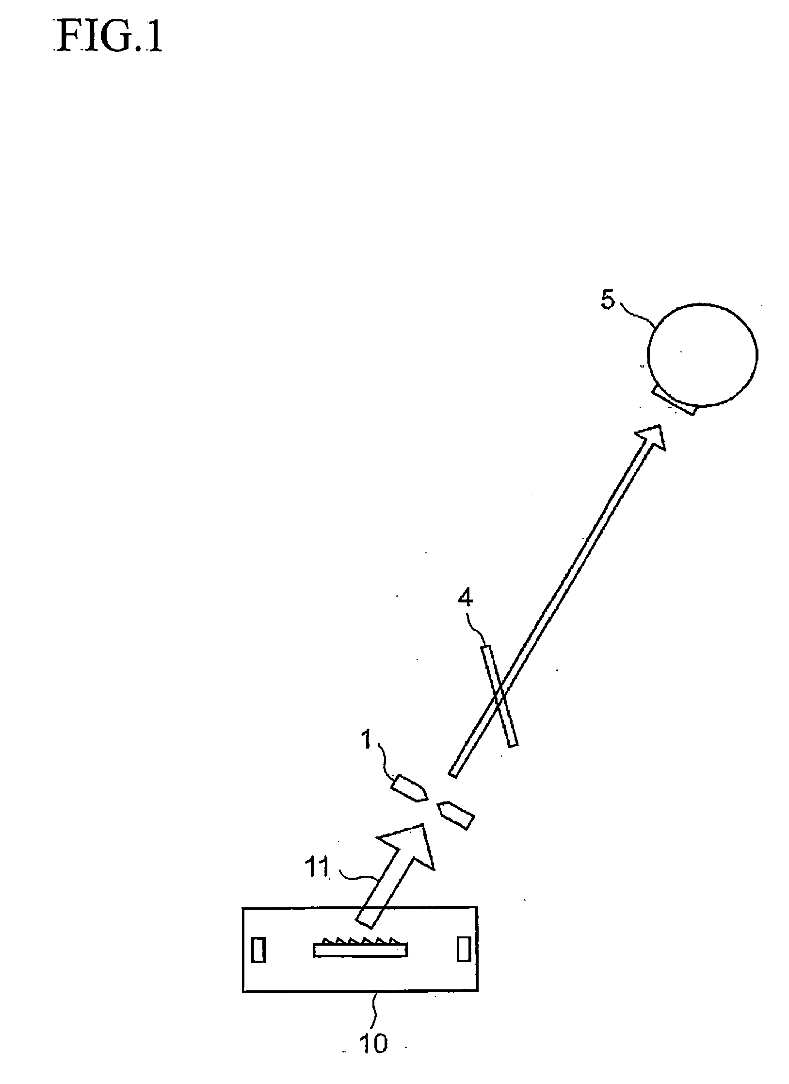
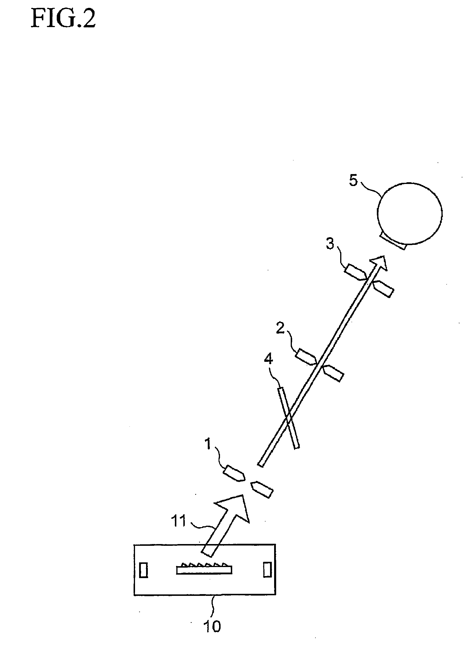
[0048] Next, an embodiment of an optical component for terahertz wave, a terahertz band wave processing apparatus and method according to the present invention will be described in detail with reference to the accompanying drawings. Referring to FIGS. 1 to 4, one embodiment of an optical component for terahertz wave, a terahertz band wave processing apparatus and method of the present invention is shown.

[0049] FIGS. 1 to 3 show a processing procedure example of coaxially superimposing a pilot beam (visible light) on terahertz waves. A processing procedure of the embodiment is constructed based on the corresponding processing of a step 1 to a step 3 shown in FIG. 1 to FIG. 3. The present alignment procedure example is shown below.

[0050] (Step 1)

[0051]FIG. 1 is a system diagram showing a configuration example of an optical component for terahertz wave, a terahertz band wave processing apparatus and method to which a step 1 is applied. In the present FIG. 1, the optical component fo...


PUM

PropertyMeasurementUnit
wavelengthsaaaaaaaaaa
thicknessaaaaaaaaaa
refractive indexaaaaaaaaaa

Abstract

A tera-hertz band wave processing device includes a tera-hertz wave generator for generating a specified tera-hertz wave, and an optics optical plane composed of a high-function resin and provided ahead of the advancing direction of a generated tera-hertz wave. A translucent plate is formed as the optics optical plane. The optical axis between the plate and the generator is regulated by a first translucence regulator to transmit a tera-hertz wave on the optical axis and reflect a light beamed at a specified incident angle off the plate. Second translucence regulators are provided on the optical axis between the plate and on Si bolometer. A specified visible light is shone to the plate as a pilot light and is allowed to reflect off the plate to superimpose the optical axis of the reflected visible light on the optical axis of a tera-hertz wave.

Description

TECHNICAL FIELD [0001] The present invention relates to an optical component for terahertz wave, a terahertz wave optical system, a terahertz band wave processing apparatus and method and, for example, relates to an optical component for terahertz wave, a terahertz band wave processing apparatus and method capable of making easier use of terahertz light more effectively. BACKGROUND ART [0002] (Patent Reference 1) [0003] JP-A-2002-303574 [0004] (Patent Reference 2) [0005] JP-A-2002-246664 [0006] (Patent Reference 3) [0007] JP-A-2002-223017 [0008] Conventionally, terahertz band electromagnetic waves are invisible light in a normal state. Such terahertz band light is electromagnetic waves present in a zone of wavelengths of 3 mm to 30 μm and frequencies of 100 GHz to 10 THz, and is used in inspection, measurement, imaging of a substance and various other fields. [0009] As described above, the terahertz light cannot be seen directly by human eyes. FIG. 5 shows a frequency distribution o...

Claims


Application Information

Patent Timeline
Patent Type & Authority Applications(United States)
IPC IPC(8): H01S3/30G01N21/35G01N21/3581G02B1/04G02B5/08G02B5/30H01S1/02
CPCG01N21/3581G02B1/04C08L65/00
Inventor MINAMIDE, HIROAKIITO, HIROMASAKUDO, AKIHITO
Owner RIKEN
Learn More