
Method and device for the pneumatic operation of a tool

Active Publication Date: 2006-12-07
CARGINE ENG AB
View PDF2 Cites 13 Cited by
  • Summary
  • Abstract
  • Description
  • Claims
  • Application Information

AI Technical Summary

Benefits of technology

[0008] The object of the invention is to provide a method and a device to satisfy the need of pressure fluid, air or other gas for the operation of a tool while, simultaneously, the heat losses appearing in the circuit are minimized.
[0009] It is a further object of the invention to provide a method and a device that permits the use of the compressor with a relatively low capacity, that is a low consumption of air energy, for the operation of a specific tool. SUMMARY OF THE INVENTION
[0011] The invention is based on the conclusion that, if the required pressure fluid is generated through compression without the contemporary temperature increase, the heat losses can be reduced to a corresponding degree, and the compressor can be made substantially smaller, which in many cases is of important advantage.
[0012] According to the present invention, the temperature increase by the compressor becomes very small as the compression is performed from an elevated pressure, higher than the pressure of the surrounding atmosphere, resulting in remarkably small heat losses for a particular absolute pressure increase. One condition is that the environment in which a conduit conducts the pressure fluid from the compressor to the tool has a certain maximum temperature which is lower than the temperature that the pressure fluid would have upon compression from atmospheric pressure up to the required pressure. Furthermore, the length of the conduit should be such that it causes heat exchange that would normally lower the temperature of the pressure fluid to the temperature of the surrounding. A realisation of the invention results in a remarkably lower compression temperature, temperature of the compressed gas, resulting in the potential for heat losses decreasing and the potential for heat supply increasing.
[0019] In the following example of the invention, it is shown how the potential for heat losses can be reduced to a remarkable degree. An adiabatic compression of atmospheric air of 1 bar absolute and a temperature of 300 K to the pressure of 10 bar absolute, that is a pressure difference of 9 bar, results in a final temperature of approximately 579 K. The potential for heat losses up to the user site, having the surrounding temperature of 300 K, is 579 minus 300, that is 279 degrees. In a closed system according to the invention, where the air pressure is 11 bar absolute and the temperature is 300 K before the adiabatic compression up to 20 bar absolute, that is a pressure difference of 9 bar, a final temperature of approximately 356 K is obtained. The potential for heat losses up to the user site is 356-300, that is 56 degrees. In the first case, the temperature becomes 279 degrees higher than the temperature of the environment, and in the latter case it becomes 56 degrees higher. The latter, inventive case results in a remarkably lower potential for heat losses to the environment. Simultaneously, the potential for 
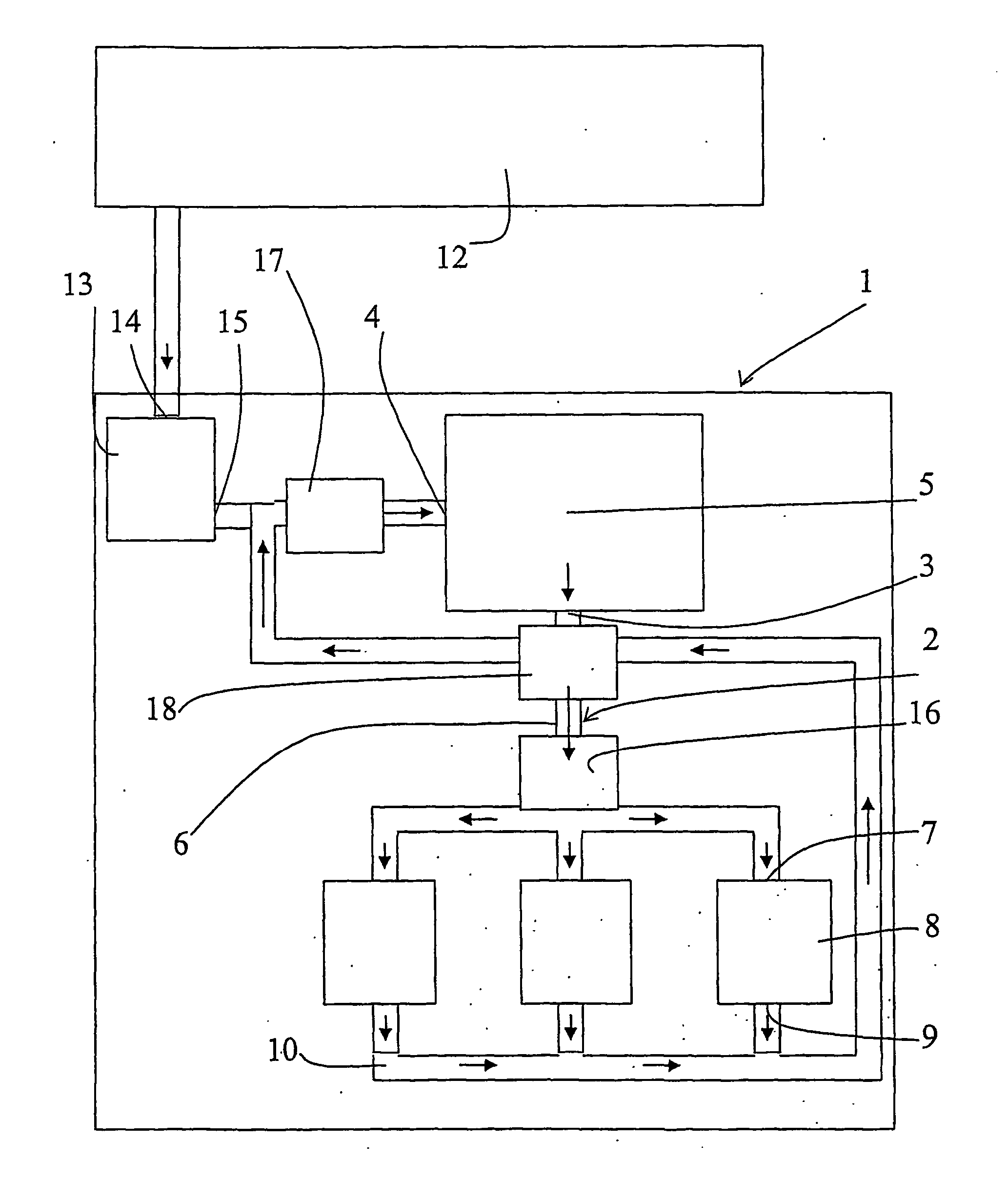
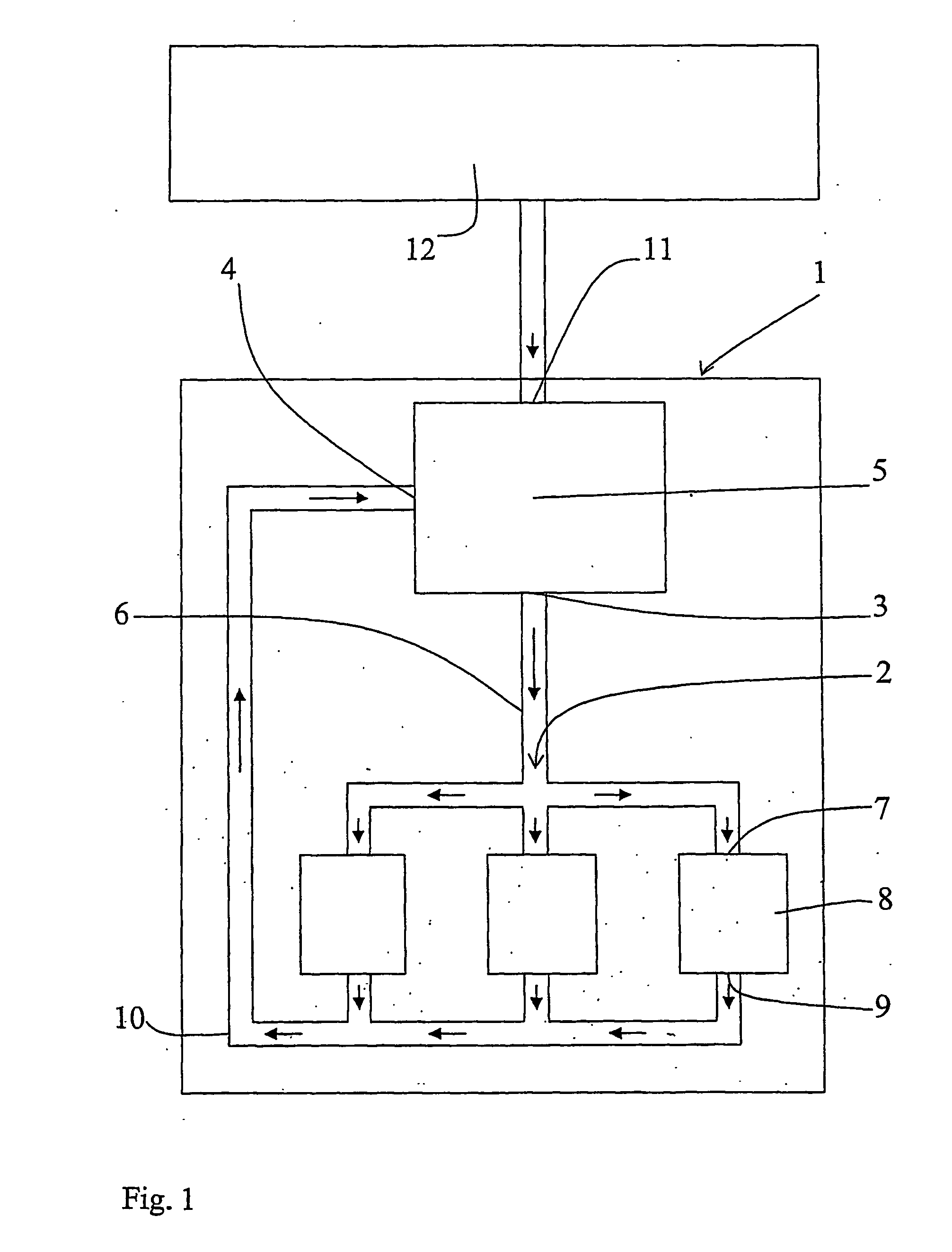
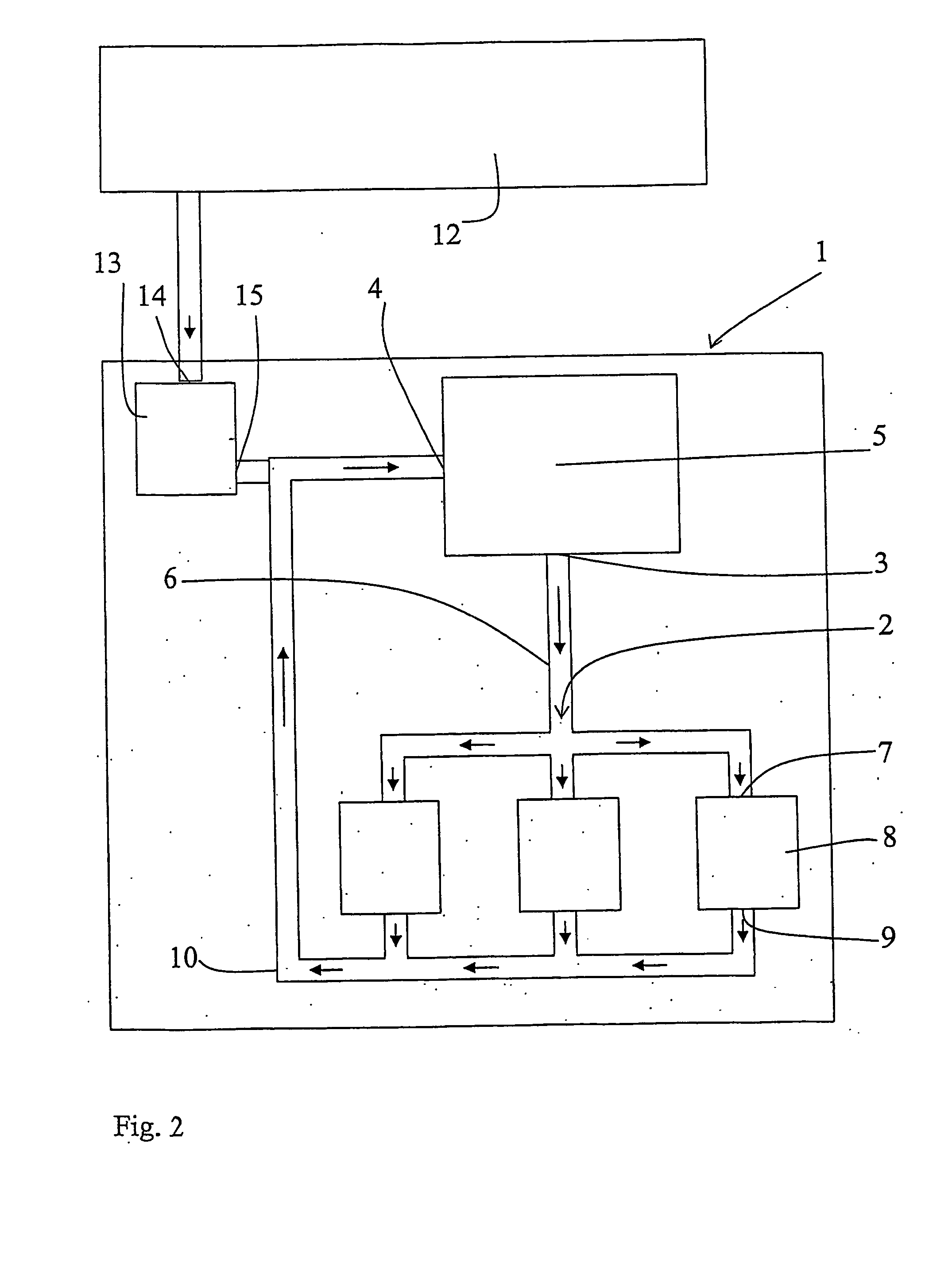
heat supply increases. According to this example, heat sources with a temperature of more than 356 K can be used for the purpose of increasing the temperature in the air compressed to 20 bar. This, in its turn, results in a volume increase which means that a smaller amount of air of 20 bar must be produced for a certain need, in its turn resulting in a decreased need of compressor work.
[0020] By the implementation of the invention, piston compressors may be substituted by smaller, for example rotating compressors with better flow capacity but operating with a low compression ratio for the purpose of maintaining the efficiency at a reasonable level. The required displacement decreases with an increased return pressure, in its turn resulting in less friction and less heat-transferring surfaces. Preferably, waste heat or any other heat source is used for heating the air, or at least minimizing the cooling thereof, before it is supplied to the working tool. Then, also a cooling of the fluid before the compression is needed. Advantageously, heat is regained from the return air before the latter is finally cooled before the compression thereof (if the temperature is higher than after the compression, which could be the result of to much heat being supplied from the heat source upstream the tool) and before any heat is supplied from the heat source. With this heating and cooling there is presented a pneumatic energy transformer, and more work is produced by, for example, a working tool or an expander than supplied by the compressor, thanks to the external supply of heat. In a closed system, the need of removal of condenser water is minimized.

Problems solved by technology

There are also other losses, but the far most important source of loss is constituted by said heat loss.
The heat loss effects the energy efficiency negatively.
An excessive amount of energy is required for the operation of a compressor for supplying, for example, pressurised air to a tool of a certain power.

Method used


Image

  • Method and device for the pneumatic operation of a tool
  • Method and device for the pneumatic operation of a tool
  • Method and device for the pneumatic operation of a tool

Examples


Embodiment Construction

[0027]FIG. 1 shows a device 1 with a generally closed pressure fluid circuit 2 which comprises at least one compressor 5, that compresses and pumps fluid with a low compression ratio and a high pressure. The fluid is transported through the compressor 5 from the inlet 4 thereof to the outlet 3 thereof upon compression. The relation between the pressure at the outlet 3 and the pressure at the inlet 4 is, for a certain absolute increase of pressure in the compressor, remarkably low in comparison to contemporary methods / devices, as the pressure at the inlet 4 exceeds the pressure of the surrounding atmosphere, and since contemporary devices operate with an inlet pressure that generally corresponds to the pressure of the surrounding atmosphere. Preferably, the inlet pressure is more than 1,5 times, preferably more than 2,0 times higher than the pressure of the surrounding atmosphere.

[0028] The fluid is guided from the compressor 5 through a conduit 6 to an inlet 7 of at least one fluid...


PUM


Abstract

A device for the pneumatic operation of a tool includes a generally closed pressure fluid circuit (2), at least one compressor (5), for increasing the pressure of the pressure fluid in the circuit, the compressor (5) having an inlet and an outlet, and a tool driven by the pressure fluid in the circuit, and through which the pressure fluid is transported in the circuit from the outlet to the inlet of the compressor (5). The pressure that is generated by the compressor and the load adopted by the tool (8) are adapted such that the pressure of the returning pressure fluid downstream the tool (8) is higher than the pressure of the surrounding atmosphere.

Description

FIELD OF THE INVENTION [0001] The present invention relates to a method for the pneumatic operation of a tool. In particular it relates to a method according to the preamble of patent claim 1. [0002] The invention also relates to a device for the implementation of the method. In particular, it relates to a device according to the preamble of the independent patent claim 6. [0003] The invention is applicable at all kinds of pneumatic devices, such as engines and tools that are operated by means of air or any other gas. Tool, as it is referred to here, should be regarded in a wide sense, including devices for any industrial use, for the pneumatic operation of vehicles, for pneumatically activated actuators for engine valves, all types of working tools etc. [0004]“Generally closed” is referred to as a circuit that is as closed as possible, that is a circuit by which there is a continuous pressure fluid conduit from the outlet of the compressor, through the operated tool to the inlet of...

Claims


Application Information

Patent Timeline
IPC IPC(8): F16D31/02F15B1/26F15B11/06F15B21/14
CPCF04B2205/01F15B1/265F15B11/06F15B2211/8855F15B2211/62F15B2211/88F15B21/14F04B49/00
Inventor HEDMAN, MATS
Owner CARGINE ENG AB
Learn More