Integrated balanced-filters

a balanced filter and filter technology, applied in the field of integrated balanced filters, can solve the problems of not having specific transmission requirements over any frequency, unable to achieve ideal balun, and never being able to address the information on how to shape up such responses, etc., and achieve the effect of reducing the size of the devi

Inactive Publication Date: 2006-12-07
THE CHINESE UNIVERSITY OF HONG KONG
View PDF14 Cites 24 Cited by
  • Summary
  • Abstract
  • Description
  • Claims
  • Application Information

AI Technical Summary

Benefits of technology

[0016] In one embodiment, the balanced-filter can provide a matching network function, a balun function and an extracted-pole bandpass filter function at the same time. Moreover, the balanced-filter can be integrated into the multi-layered substrate, thereby reducing the size of the device.

Problems solved by technology

However, they do not have specific transmission requirements over any frequency other than those within the operating frequency band.
While prior art have analyzed some topologies that offer a bandpass-type of transmission response, information on how to shape up such response has never been addressed nor is the primary concern of them.
In practice, however, such an ideal balun is hard to be realized due to the requirement of a high magnetic coupling.

Method used


Image

  • Integrated balanced-filters
  • Integrated balanced-filters
  • Integrated balanced-filters

Examples


first embodiment

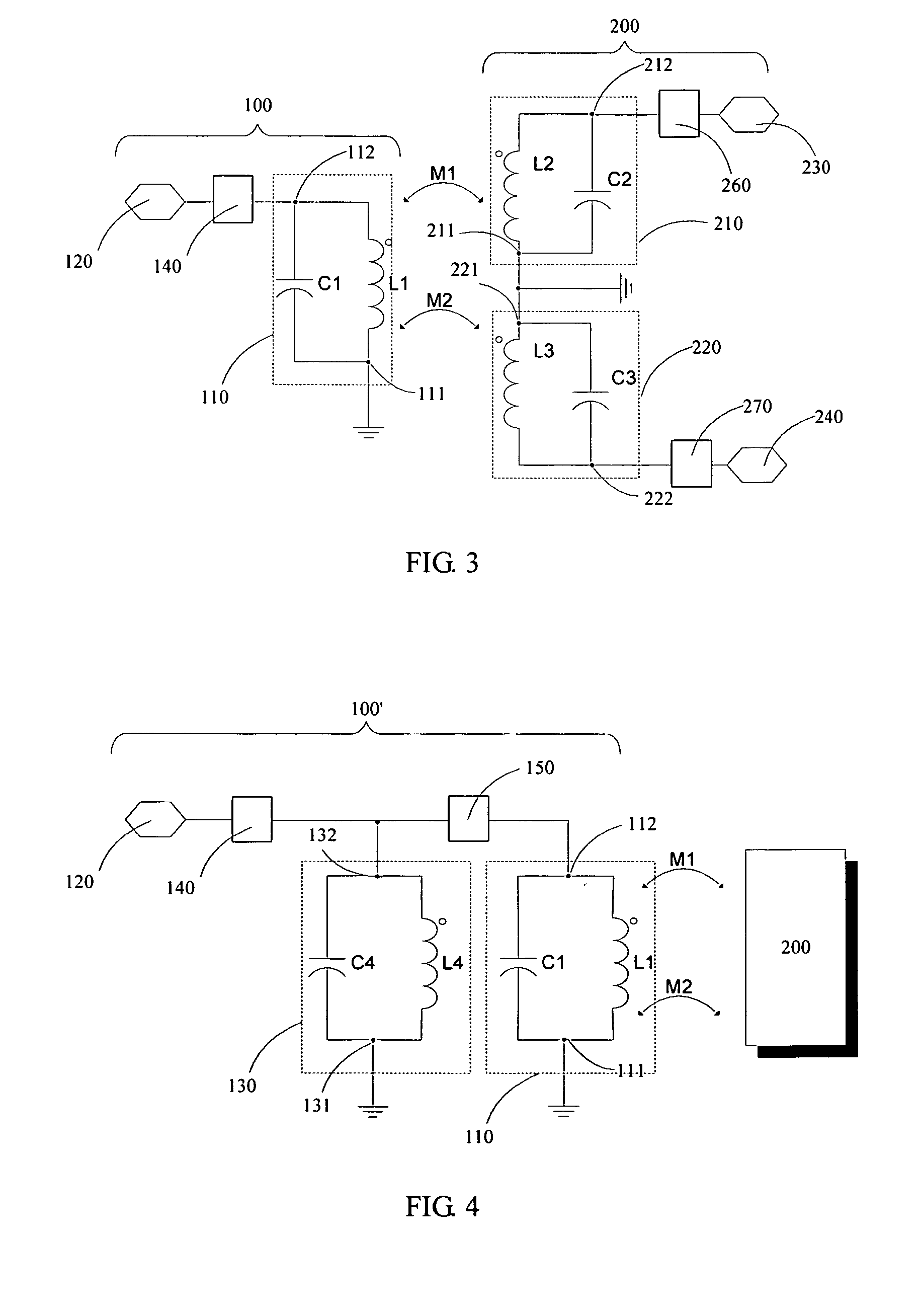
[0031]FIG. 3 is a schematic diagram illustrating the configuration of a balanced-filter according to the invention. The balanced-filter of the embodiment comprises a first electrical circuit 100 and a second electrical circuit 200. The first electrical circuit 100 includes an unbalanced terminal 120 for transceiving an unbalanced signal, and a first resonator 110 having a first node 111 connected to the ground and a second node 112 connected to the unbalanced terminal 120 through a coupling element 140. The second electrical circuit 200 includes a first balanced terminal 230 and a second balanced terminal 240 for transceiving a balanced signal, a second resonator 210 having a first node 211 connected to the ground and a second node 212 connected to the first balanced terminal 230 through a coupling element 260, and a third resonator 220 having a first node 221 connected to the ground and a second node 222 connected to the second balanced terminal 240 through a coupling element 270.

[...

third embodiment

[0041] According to the invention, the balanced-filter may further comprise a notch filter for notch-filtering the balanced signals at a rejected frequency. As shown in FIG. 5, the balanced-filter of the present embodiment comprises the first electrical circuit 100′ as described above, and a second electrical circuit 200′. In the second electrical circuit 200′, the coupling elements 260 and 270 are replaced by a first notch filter 260′ and a second notch filter 270′. The first notch filter 260′, which includes a fifth capacitive element CX1 and a fifth inductive element LX1 connected in parallel to the fifth capacitive element CX1, has a first node 261 connected to the second node 212 of the second resonator 210, and a second node 262 connected to the first balanced terminal 230. Similarly, the second notch filter 270′, which includes a sixth capacitive element CX2 and a sixth inductive element LX2 connected in parallel to the sixth capacitive element CX2, has a first node 271 conne...

second embodiment

[0045] According to one embodiment of the present invention, a conventional coupled-resonator theory can be used to design the integrated balanced-filter having a balun function and a bandpass filtering function as shown in FIGS. 3 and 4. For example, a method for designing the balanced-filter of the second embodiment as shown in FIG. 4, which provides the balun function and the third-order bandpass filtering function, comprises the following steps:

[0046] 1. Calculating prototype component values of a third-order bandpass filter using the table given in reference [8] (G L. Matthaei, L. Young, and E. M. T. Jones, Microwave Filters, Impedance Matching Networks and Coupling Structures, New York: McGraw-Hill, 1980), in which an inductive-type impedance inverter can be used between the first and the second resonators, as well as between the first and the third resonators;

[0047] 2. Converting the series inductive elements between the first, the second and the third resonators to a mutual...


PUM


Abstract

An integrated balanced-filter which acts as a matching network, a balun and an extracted-pole bandpass filter is disclosed. The balanced-filter includes an unbalanced terminal, a first balanced terminal and a second balanced terminal, a first resonator connected to the unbalanced terminal, a second resonator connected to the first balanced terminal, and a third resonator connected to the second balanced terminal. The second resonator is positively coupled to the first resonator, and the third resonator is negatively coupled to the first resonator, which provides a balun function and a bandpass-filtering function. The balanced-filter further includes extracted-pole notch filters, which can introduce a transmission zero and implement matching network. The balanced-filter can be implemented in a multi-layered substrate, thereby reducing the size of the balanced-filter.

Description

RELATED APPLICATIONS [0001] This application claims the benefit of U.S. provisional patent application No. 60 / 686,977 filed Jun. 3, 2005 which is explicitly incorporated by reference in its entirety.TECHNICAL FIELD OF THE INVENTION [0002] This invention relates to an integrated balanced-filter for converting an unbalanced signal into a balanced signal or vice versa, and for bandpass-filtering the signal being converted. BACKGROUND OF THE INVENTION [0003] There is an ever increasing demand for fast, reliable and ad-hoc wireless data transfer between two or more terminal devices. Typical applications include mobile phones, laptop computers, cameras and printers. To satisfy such a demand, each of these devices should be equipped with a RF front-end module. In any case, miniaturization and low power consumption are the two most fundamental prerequisites for RF front-end modules. [0004] One way to miniaturize a RF front-end module is to embed its passive circuitries, such as antenna, ban...

Claims


Application Information

Patent Timeline
Patent Type & Authority Applications(United States)
IPC IPC(8): H01P1/203H01P5/10
CPCH03H7/38H03H2001/0085H03H7/42
Inventor YEUNG, LAP KUNWU, KE LI
Owner THE CHINESE UNIVERSITY OF HONG KONG
Why Eureka
Try Eureka