Hydrodynamic bearing device and disk rotating apparatus

Active Publication Date: 2006-12-07
PHC HLDG CORP
View PDF4 Cites 15 Cited by
  • Summary
  • Abstract
  • Description
  • Claims
  • Application Information

AI Technical Summary

Benefits of technology

[0011] In the present invention, the reservoir and the covered region are communicated with each other by the communication path. Thus, the lubricant filled in the clearance between the shaft and the bearing bore of the sleeve is circulated by way of the communication path during operation of the hydrodynamic bearing device. By circulation of the lubricant, air such as air bubbles mixed into the lubricant is also circulated together with the lubricant. When the air bubbles contained in the lubricant have reached the reservoir during the circulation, the air bubbles are separated from the lubricant and are discharged outwardly. Since the air in the lubricant is automatically removed during operation of the hydrodynamic bearing device in this way, air mixed into the lubricant d

Problems solved by technology

For example, in case ambient pressure has changed during transport in an aircraft, penetration of air bubbles may happen.
If the oil 42 leaks outwardly, shortage of quant

Method used


Image

  • Hydrodynamic bearing device and disk rotating apparatus
  • Hydrodynamic bearing device and disk rotating apparatus
  • Hydrodynamic bearing device and disk rotating apparatus

Examples


first embodiment

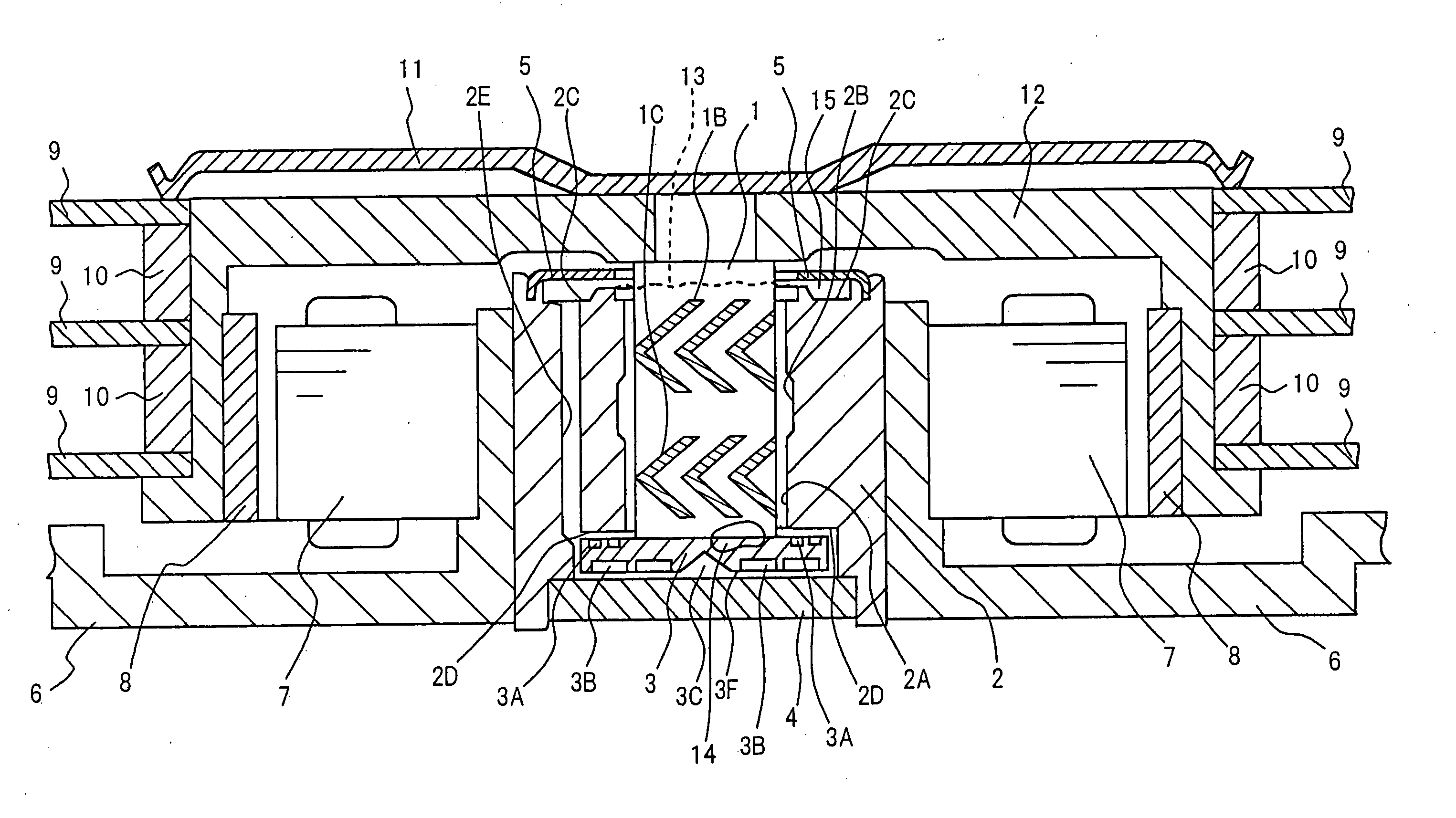
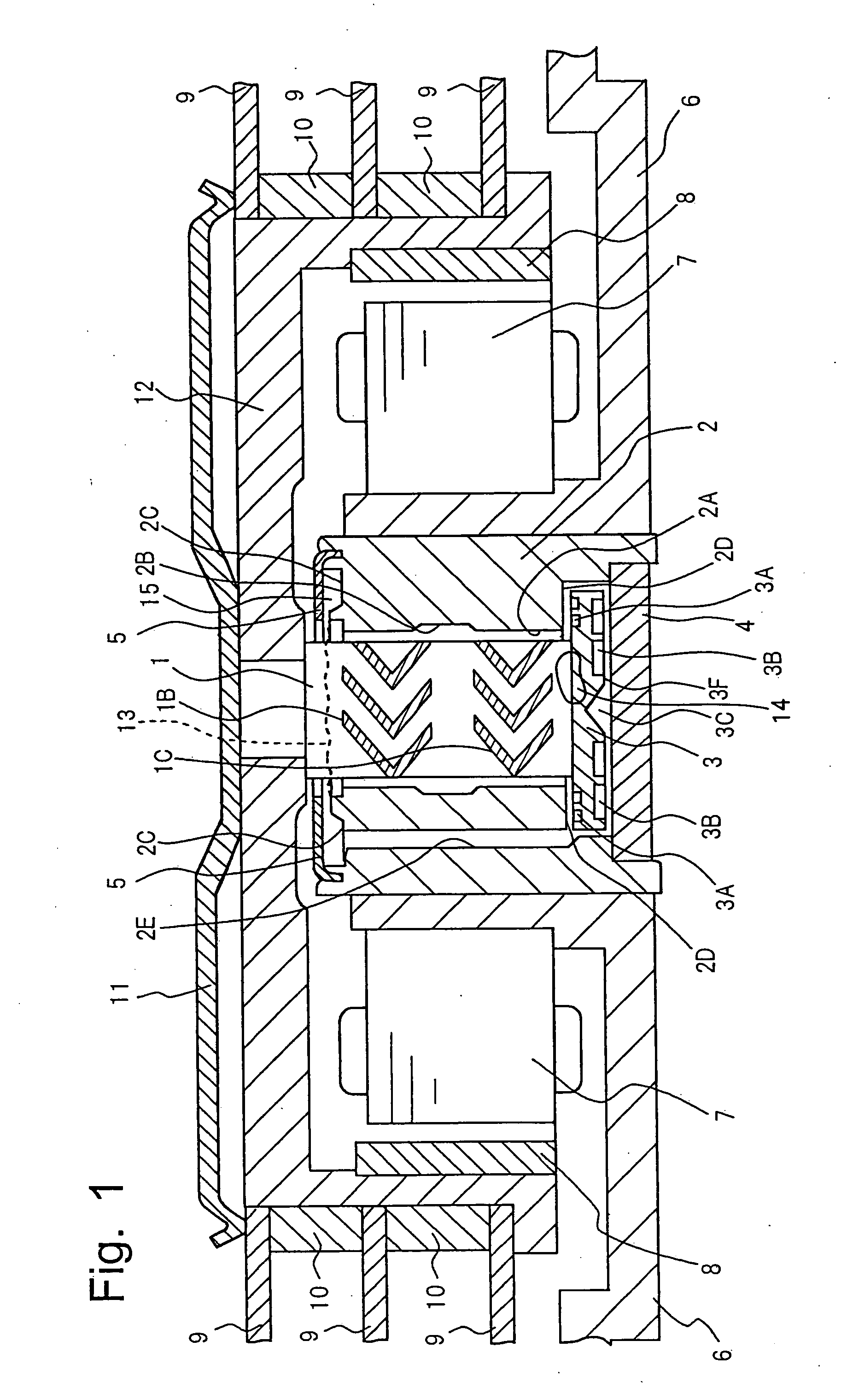
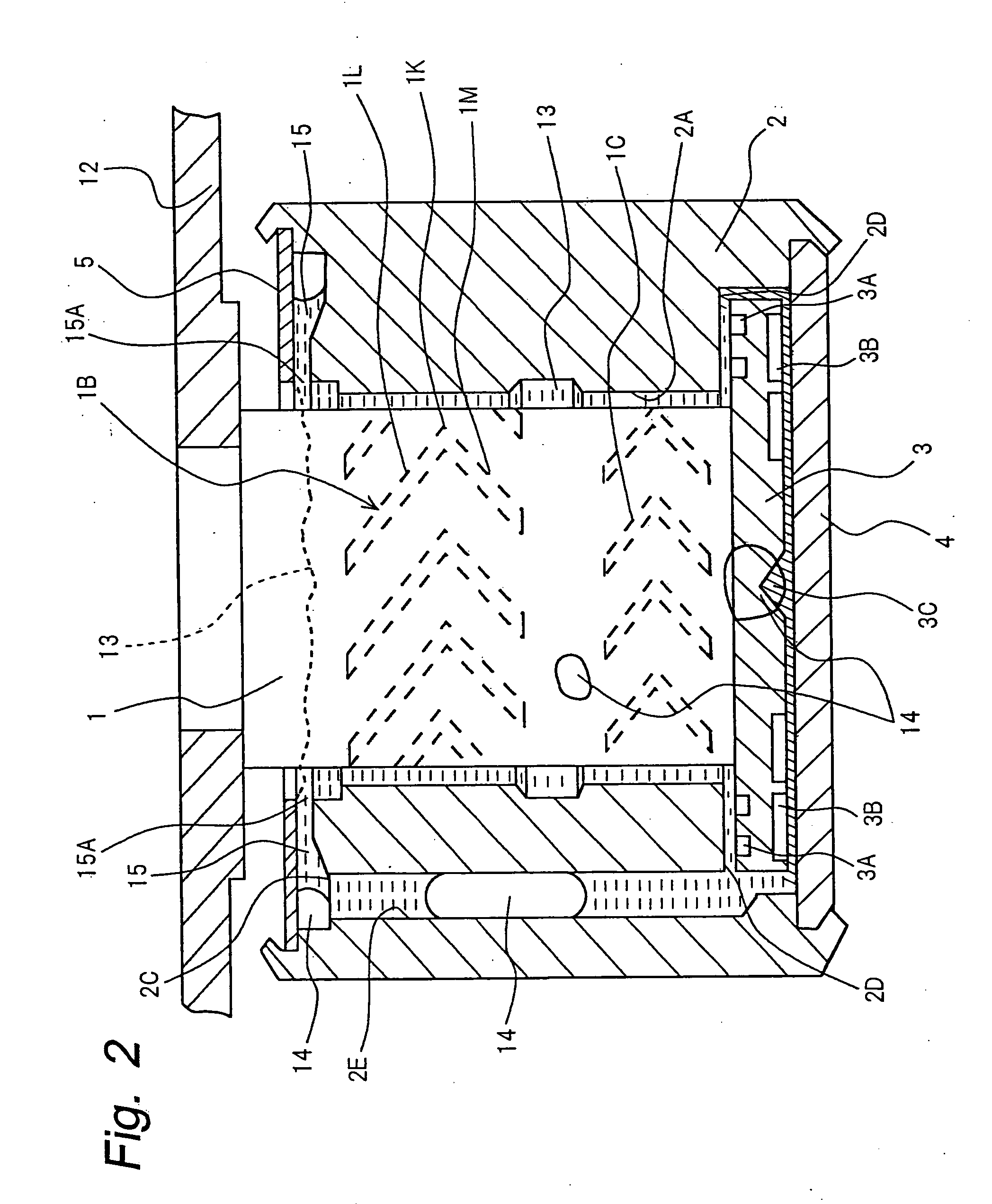
[0035] A hydrodynamic bearing device according to a first embodiment of the present invention is described with reference to FIGS. 1 to 7. FIG. 1 is a sectional view of the hydrodynamic bearing device of the first embodiment of the present invention, while FIG. 2 is an enlarged fragmentary sectional view showing a shaft 1 and a sleeve 2. In FIG. 1, the sleeve 2 has a bearing bore 2A and the cylindrical shaft 1 is rotatably inserted into the bearing bore 2A. There is a minute clearance between an outer peripheral surface of the shaft 1 and an inner peripheral surface of the bearing bore 2A of the sleeve 2. Dynamic pressure generating grooves 1B and 1C of a known herringbone pattern in which each groove is bent at an angular portion are formed on at least one of the outer peripheral surface of the shaft 1 and the inner peripheral surface of the bearing bore 2A of the sleeve 2 so as to act as a radial bearing portion. The radial bearing portion supports the shaft 1 in a radial directio...

second embodiment

[0049]FIG. 8 is a fragmentary sectional view showing the shaft 1 and a sleeve 20 of a hydrodynamic bearing device according to a second embodiment of the present invention. In FIG. 8, a second communication hole 20J for establishing communication between the first communication hole 2E and a large clearance portion 20B is provided at a central portion of the sleeve 20. Other constructions of this hydrodynamic bearing device are similar to those of the hydrodynamic bearing device of the first embodiment shown in FIG. 1.

[0050] In order to form the second communication hole 20J, there is, for example, a method in which as shown in FIG. 8, a hole is formed on the sleeve 20 in a direction of the arrow 20H with a drill. After the hole has been formed on the sleeve 20, a hole 20K on the outer periphery of the sleeve 20 is sealed with a plug 17.

[0051] In the hydrodynamic bearing device of this embodiment, the first communication hole 2E communicates with space between the dynamic pressure...

third embodiment

[0053]FIG. 9 is a fragmentary sectional view showing a shaft 30 and the sleeve 2 of a hydrodynamic bearing device according to a third embodiment of the present invention. In FIG. 9, a small diameter portion 30A having a diameter smaller than that of the shaft 30 is provided on the shaft 30 in the vicinity of an end portion of the shaft 30 coupled with the rotor hub 12. A diameter of an inner peripheral edge 25A of a ringlike cover plate 25 is larger than that of the small diameter portion 30A but is smaller than that of the shaft 30. Namely, the cover plate 25 is arranged to cover the clearance between the shaft 30 and the sleeve 2. Other constructions of this hydrodynamic bearing device are similar to those of the first embodiment shown in FIG. 1. By this arrangement, it is possible to further positively prevent outward leakage of the oil 13 from the clearance between the shaft 30 and the cover plate 25. Meanwhile, since the diameter of the inner peripheral edge 25A of the cover p...


PUM


Abstract

In a hydrodynamic bearing device in which a radial bearing face having a dynamic pressure generating groove on a shaft or an inner periphery of a sleeve is provided and a clearance between the shaft and the sleeve is filled with lubricant, an annular depression is provided on one end face of the sleeve adjacent to a rotor hub and a cover plate for covering the depression is attached to the sleeve so as to define a reservoir for the lubricant or air for the purpose of preventing such a risk that absence of an oil film occurs in clearances of a bearing of the hydrodynamic bearing device due to outflow of oil upon forcing of the oil by air received into the bearing. A step portion is provided on the other end face of the sleeve such that the step portion and the reservoir are communicated with each other by a communication hole. During operation of the hydrodynamic bearing device, air in the hydrodynamic bearing device reaches the reservoir via the communication hole so as to be discharged from the reservoir.

Description

TECHNICAL FIELD [0001] The present invention relates to a hydrodynamic bearing device for use in a main shaft portion of a rotary device requiring high-speed and high precision rotations and a disk rotating apparatus provided with the hydrodynamic bearing device. BACKGROUND ART [0002] In recent rotational recording apparatuses employing a magnetic disk, etc., data-transfer velocity is rising upon increase of their storage capacity. Hence, since a disk rotating apparatus employed in such recording apparatuses requires high-speed and high precision rotations, a hydrodynamic bearing device is used in a rotary main shaft portion of the disk rotating apparatus. [0003] Hereinafter, a conventional hydrodynamic bearing device is described with reference to FIGS. 18 and 19. In FIG. 18, a shaft 31 is rotatably inserted into a bearing bore 32A of a sleeve 32 mounted on a base 35. In FIG. 18, the shaft 31 has a flange 33 formed integrally at its lower end portion. The flange is received in a st...

Claims


Application Information

Patent Timeline
IPC IPC(8): G11B17/02F16C17/10F16C33/10
CPCF16C17/107F16C33/107F16C33/103F16C2370/12
Inventor ASADA, TAKAFUMISAITO, HIROAKIYOSHITSUGU, TAKAOKUSAKA, KEIGOKIRIYAMA, HIROYUKIITO, DAISUKE
Owner PHC HLDG CORP
Why Eureka
Try Eureka