
Gas laser apparatus

Inactive Publication Date: 2006-12-07
FANUC LTD
View PDF4 Cites 8 Cited by
  • Summary
  • Abstract
  • Description
  • Claims
  • Application Information

AI Technical Summary

Benefits of technology

[0011] It is an object of the present invention to provide a gas laser apparatus using gases as laser media, which can optimize the characteristics of a laser beam by directly adjusting the composition of a medium gas as used, in response to changes in the attributes of an object matter acted on by the laser beam and / or the required accuracy of action of the laser beam.

Problems solved by technology

However, the reduction in the formation of laminar flow and / or pulsation of the medium gas is contradictory to an increase in laser beam power.
However, it has not been attempted conventionally to optimize the characteristics (or quality) of the laser beam by directly adjusting the composition of the medium gas as used, in response to changes in the attributes of the workpiece and / or the accuracy of processing.
From this point of view, the technique as set forth in JP-A-63-42188 described above is directed mainly to the switching of the oscillation type of the laser beam between the continuous wave (CW) type and the pulse type, and therefore it is difficult in the case of this technique to optimize the characteristics (or quality) of the laser beam so as to correspond flexibly to changes in the attributes of the workpiece and / or the accuracy of processing.

Method used


Image

  • Gas laser apparatus
  • Gas laser apparatus
  • Gas laser apparatus

Examples


Embodiment Construction

[0023] The embodiments of the present invention are described below in detail, with reference to the accompanying drawings. In the drawings, the same or similar components are denoted by common reference numerals.

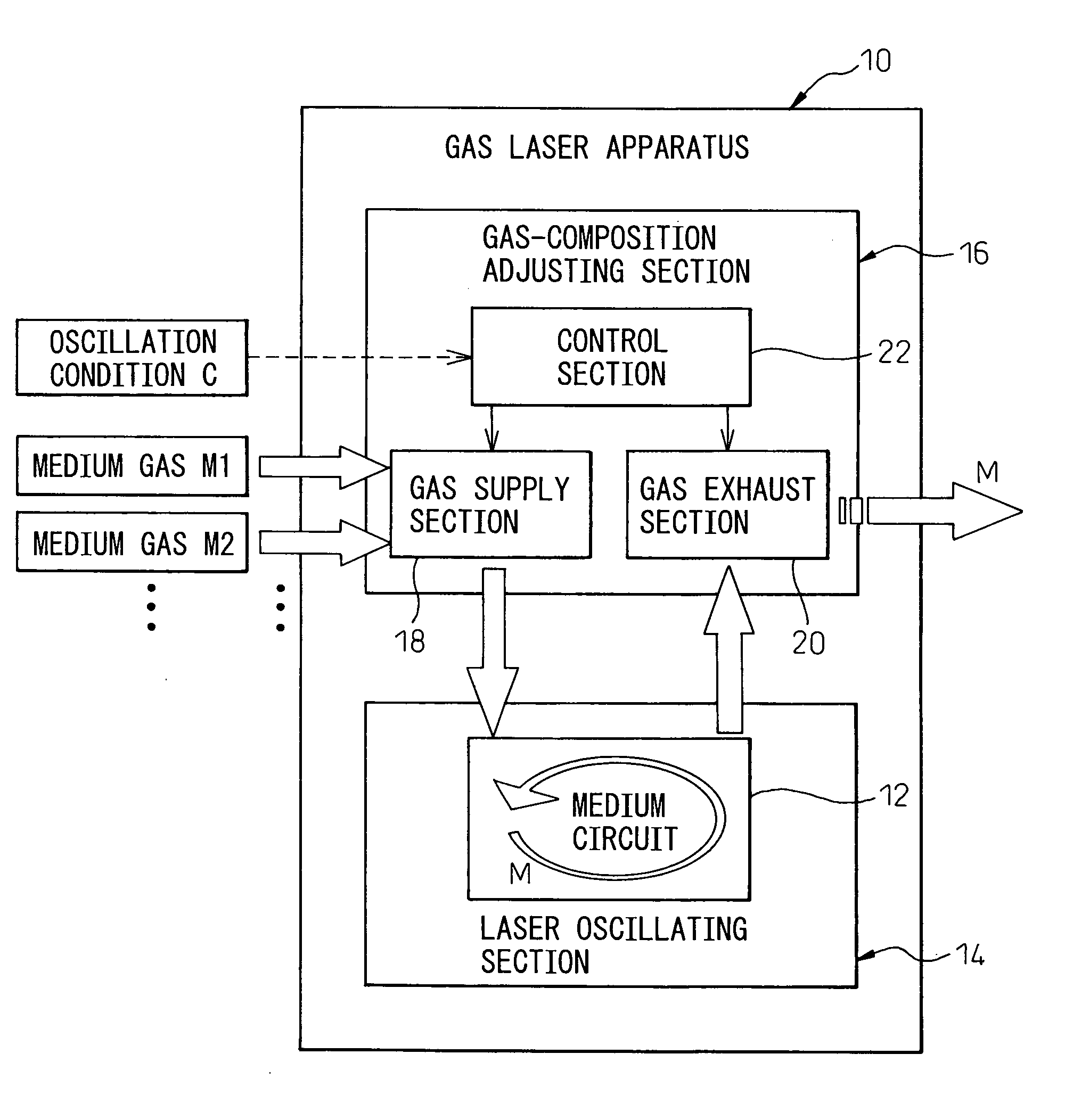
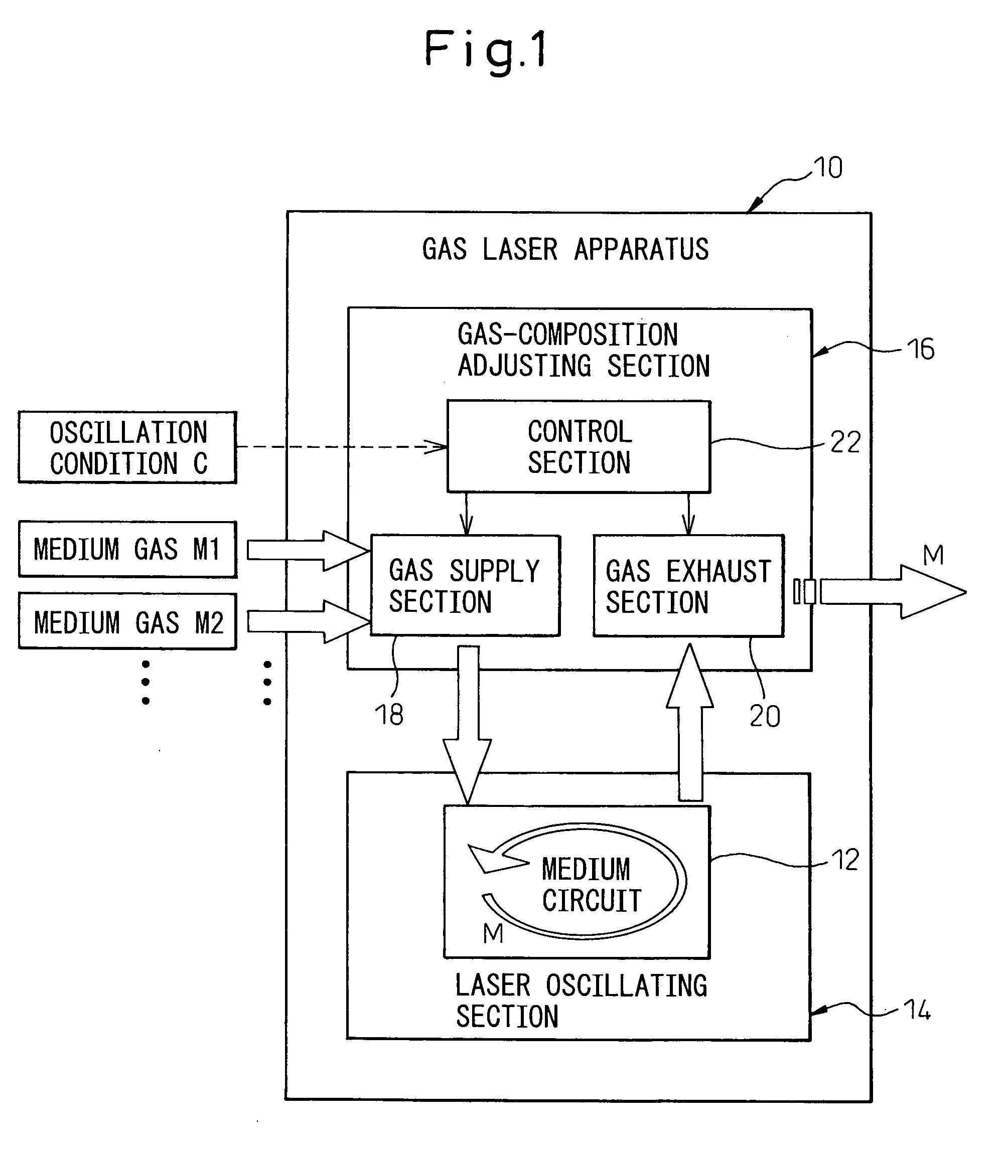
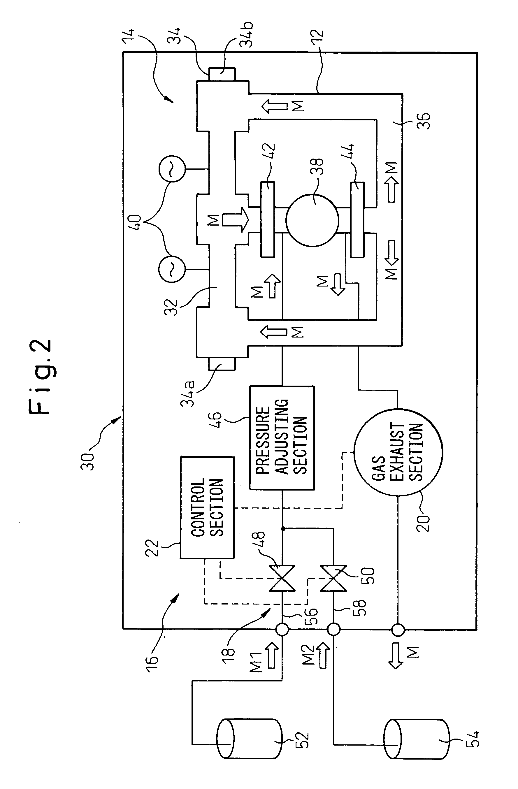
[0024] Referring to the drawings, FIG. 1 is a functional block diagram showing a basic configuration of a gas laser apparatus 10 according to the present invention. The gas laser apparatus 10 includes a laser oscillating section 14 provided with a medium circuit 12 allowing a medium gas M to flow therethrough under pressure; and a gas-composition adjusting section 16 for adjusting the composition of the medium gas M flowing through the medium circuit 12 of the laser oscillating section 14. The gas-composition adjusting section 16 includes a gas supply section 18 for supplying the medium circuit 12 of the laser oscillating section 14 with several types of medium gases M (M1, M2, . . . ) having different compositions in a manner such that the flow rate of each of the medium ...


PUM


Abstract

A gas laser apparatus including a laser oscillating section including a medium circuit allowing a medium gas to flow therethrough under pressure, and a gas-composition adjusting section for adjusting the composition of the medium gas flowing through the medium circuit of the laser oscillating section. The gas-composition adjusting section comprising a gas supply section for supplying several types of medium gases having different compositions to the medium circuit of the laser oscillating section with a flow rate of each of the medium gases being adjustable; a gas exhaust section for exhausting the medium gas from the medium circuit of the laser oscillating section; and a control section for controlling the gas supply section and the gas exhaust section, to adjust the composition of the medium gas flowing through the medium circuit, in accordance with an oscillation condition including at least one of an attribute of an object matter acted on by a laser beam oscillated by the laser oscillating section and the accuracy of action of the laser beam.

Description

BACKGROUND OF THE INVENTION [0001] 1. Field of the Invention [0002] The present invention relates to a gas laser apparatus using gases as laser media. [0003] 2. Description of the Related Art [0004] A gas laser apparatuses using gases as laser media is widely employed in the field of processing, medical care, measurement and so on. A laser oscillator constituting the gas laser apparatus generally includes an excitation section for exciting (by electrical discharge, light, heat, chemical reaction and the like) a flowable gas acting as a laser medium (referred to as a medium gas in this application); a light resonance section (having a pair of mirrors) for amplifying light energy of the medium gas excited by the excitation section and emitting the amplified light energy as a laser beam; a circulation path connected with the excitation section and the light oscillation section to form a medium circuit in which the medium gas flows under pressure; and a blower disposed in the circulatio...

Claims


Application Information

Patent Timeline
IPC IPC(8): H01S3/22H01S3/223
CPCH01S3/036H01S3/2232H01S3/104
Inventor SATO, TAKANORIMURAKAMI, TAKAFUMIEGAWA, AKIRA
Owner FANUC LTD
Learn More