Method to enable single frequency network optimization

a single frequency network and optimization technology, applied in the field of digital data transmission, can solve the problems of increasing the amount of distortion, affecting the overall performance of both level 1 and level 2 data, and requiring a non-coherent receiver to decode the signal, so as to reduce the interference in signal transmission, improve performance, and optimize the infrastructure more efficiently

Active Publication Date: 2006-12-07
APTIV TECH LTD
View PDF8 Cites 3 Cited by
  • Summary
  • Abstract
  • Description
  • Claims
  • Application Information

AI Technical Summary

Benefits of technology

[0010] Intersymbol interference (ISI) describes the situation where the energy from one symbol spills over into another symbol resulting in signal distortion. ISI is caused by the frequency selectivity (time dispersion) of the channel due to multipath propagation. Doppler shift describes the random changes in the channel introduced as a result of a user's mobility and the relative motion of objects in the channel. Doppler has the effect of shifting, or spreading, the frequency components of a signal resulting in signal fades.
[0011] Some terrestrial audio broadcast systems use differential multiple phase shift keying (D-MPSK) modulation (e.g., D-BPSK, D-QPSK, pi/4 D-QPSK). Standard differential modulation techniques like D-MPSK encode the data in the phase difference between two consecutive PSK symbols. A D-MPSK modulation technique may be accomplished by transmitting the phase information across adjacent orthogonal frequency-division multiplexing (OFDM) symbols or adjacent frequency subcarriers. OFDM works by splitting the radio signal into multiple smaller sub-signals that are then transmitted simultaneously at diff

Problems solved by technology

However, differential modulation (D-MPSK), as transmitted by the conventional SDAR terrestrial repeaters, only requires a non-coherent receiver to decode the signal.
As additional data is added to a signa

Method used


Image

  • Method to enable single frequency network optimization
  • Method to enable single frequency network optimization
  • Method to enable single frequency network optimization

Examples


Embodiment Construction

[0021] The embodiments disclosed below are not intended to be exhaustive or limit the invention to the precise forms disclosed in the following detailed description. Rather, the embodiments are chosen and described so that others skilled in the art may utilize their teachings.

[0022] For the purposes of the present invention, certain terms shall be interpreted accordance with the following definitions.

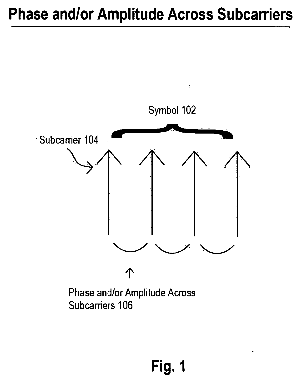
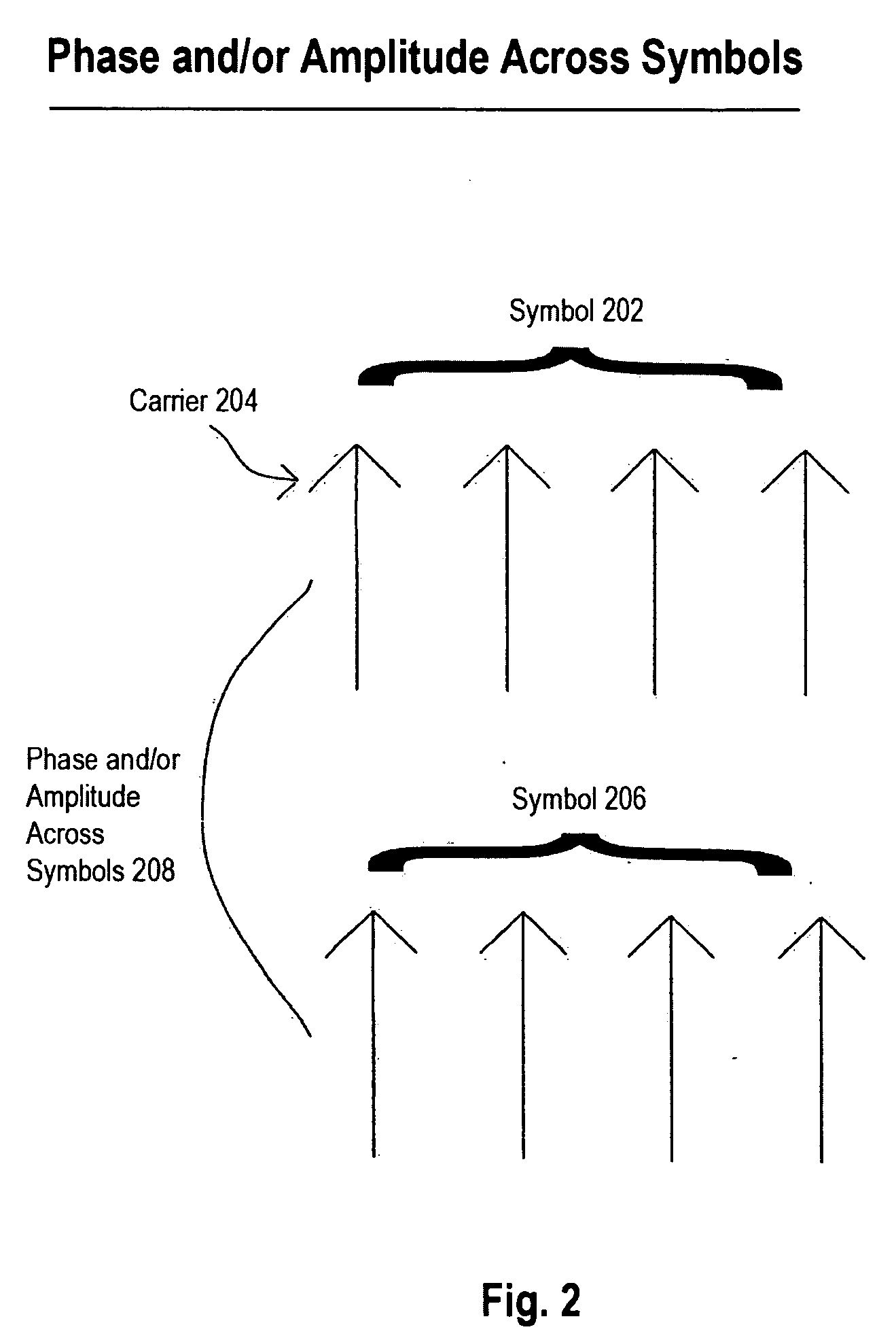
[0023]“Orthogonal frequency division multiplexing” or “OFDM” hereinafter refers to the communications technique that divides a communications channel into a number of equally spaced frequency bands. A subcarrier carrying a portion of the data is transmitted in each band. Each subcarrier is independent of every other subcarrier.

[0024]“Phase shift keying” or “PSK” hereinafter refers to a method of transmitting and receiving digital signals in which the phase of a transmitted signal is varied to convey information. Phase may also be an expression of relative displacement between or amon...


PUM


Abstract

Additional data may be added to the current SDARS satellite signals as a phase and/or amplitude offset from the legacy quadrature phase shift keying (QPSK) modulated data and transmitted by the SDAR terrestrial repeaters. However, in the case where a legacy receiver architecture for a differential modulation system outputs angular/phase differences between carriers, the phase and/or amplitude information appears as distortion to the legacy receiver. The present invention provides a method for optimizing the SDARS infrastructure more efficiently by allowing independent adjustment of the phase and/or amplitude offset (610) at each terrestrial site. The present invention provides a method for adjusting the performance of each signal together or separately as needed.

Description

TECHNICAL BACKGROUND [0001] The present invention generally relates to the transmission of digital data, and more particularly, to the transmission of digital data in a satellite digital audio radio (“SDAR”) system. BACKGROUND OF THE INVENTION [0002] In October of 1997, the Federal Communications Commission (FCC) granted two national satellite radio broadcast licenses. In doing so, the FCC allocated 25 megahertz (MHz) of the electromagnetic spectrum for satellite digital broadcasting, 12.5 MHz of which are owned by XM Satellite Radio, Inc. of Washington, D.C. (“XM”), and 12.5 MHz of which are owned by Sirius Satellite Radio, Inc. of New York City, N.Y. (“Sirius”). Both companies provide subscription-based digital audio that is transmitted from communication satellites, and the services provided by these—and eventually other—companies (i.e., SDAR companies) are capable of being transmitted to both mobile and fixed receivers on the ground. [0003] In the XM satellite system, two commun...

Claims


Application Information

Patent Timeline
IPC IPC(8): H04L27/20
CPCH04H20/30H04L27/2604H04L27/183H04H20/67
Inventor DIBIASO, ERIC A.HIATT, MICHAEL L. JR.WALKER, GLENN A.
Owner APTIV TECH LTD
Why Eureka
Try Eureka