Clock pulse control device of a microwave pulse radar

a control device and pulse radar technology, applied in the direction of reradiation, transmission, liquid/fluent solid measurement, etc., can solve the problem of increasing the space in time in which regulation can become activ

Inactive Publication Date: 2006-12-07
VEGA GRIESHABER GMBH & CO
View PDF20 Cites 16 Cited by
  • Summary
  • Abstract
  • Description
  • Claims
  • Application Information

AI Technical Summary

Problems solved by technology

However, the smaller the frequency difference set, the more problematical exact regulation of the frequency difference, because measuring the differential frequency requires the time duration corresponding to a full period, for example from one rising flank of the square-wave signal to the next one, so that the space in time in which regulation can become active becomes increasingly large as the differential frequency decreases.

Method used


Image

  • Clock pulse control device of a microwave pulse radar
  • Clock pulse control device of a microwave pulse radar
  • Clock pulse control device of a microwave pulse radar

Examples


Embodiment Construction

[0052] Identical or similar components in different figures have the same reference characters. The illustrations in the figures are diagrammatic and not to scale.

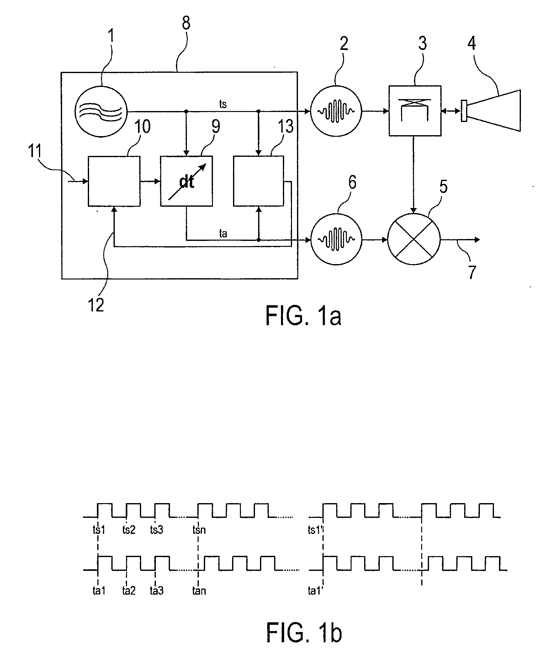
[0053]FIG. 1a shows a sampling circuit of a pulse radar in the form of a block diagram.

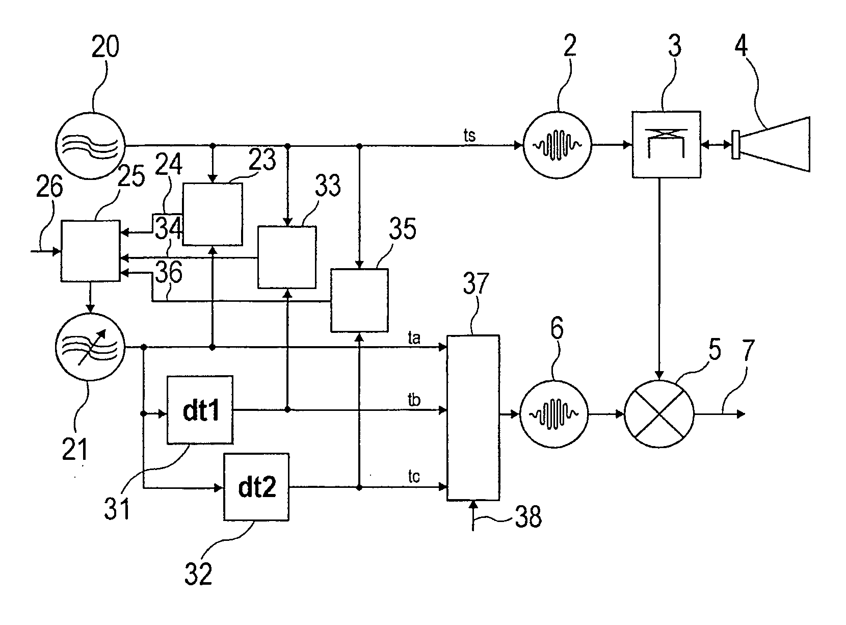
[0054] An oscillator 1 generates a transmit clock pulse ts, which by triggering a transmit pulse generator 2 controls generation of transmit pulses. By way of the directional coupler 3 the transmit pulses generated in this way are predominantly conveyed to the antenna 4 and from the latter are eradiated in the direction of the surface of the product contained in the container. The pulses reflected in the container by the product contained in the container are received after an interval that corresponds to their run time and, by way of the directional coupler 3, are conveyed, as a receive signal, to the sampling mixer 5. There, by means of sampling pulses that are generated in the sampling pulse generator 6, sampling values are taken fr...


PUM


Abstract

The invention relates to a clock pulse control circuit for generating a transmit clock pulse (ts) and a sampling clock pulse (ta; tb; tc), wherein the clock pulse control circuit comprises a first oscillator (20) for generating a first clock pulse (ts) of a first frequency, and a second oscillator (21) for generating a plurality of second clock pulses (ta; tb; tc), that are shifted in time in relation to each other, of a second frequency. The clock pulse control circuit is designed such that based on the first clock pulse (ts) and the plurality of second clock pulses (ta; tb; tc) the transmit clock pulse (ts) is providable to a transmit pulse generator (2), and the sampling clock pulse (ta; tb; tc) is providable to a sampling pulse generator (6).

Description

REFERENCE TO RELATED APPLICATIONS [0001] This application claims the benefit of the filing date of U.S. Provisional Patent Application No. 60 / 681,644 filed May 17, and of German Patent Application No. 10 2005 022 558.6 filed May 17, 2005, the disclosure of which applications are hereby incorporated herein by reference.FIELD OF THE INVENTION [0002] The present invention relates to a clock pulse control device and a method for generating certain transmit- and sampling clock pulses, and to a distance measuring device for measuring distances. BACKGROUND OF THE INVENTION [0003] For continuously measuring the fill level of liquids and solids in containers, utilising measurement of the run time of electromagnetic waves, measuring devices are usually installed on or in the ceiling of the container, wherein said measuring devices subsequently transmit waves, either guided through a waveguide or radiated by way of an antenna, in the direction of the product contained in the container. The wav...

Claims


Application Information

Patent Timeline
Patent Type & Authority Applications(United States)
IPC IPC(8): H04L7/00
CPCG01F23/284G01S7/28H03K5/135G01S13/18G01S7/288
Inventor GRIESSBAUM, KARL
Owner VEGA GRIESHABER GMBH & CO
Why Eureka
Try Eureka