
Substrate and device for bioassay and method for making the substrate

a bioassay and substrate technology, applied in the direction of liquid/fluent solid measurement, fluid pressure measurement, peptides, etc., can solve the problems of unstable reading of inability to read positional information and substance information of the information pit group, and inability to read information from the information pit group. to achieve more stably obtained

Inactive Publication Date: 2006-12-07
SONY CORP
View PDF7 Cites 16 Cited by
  • Summary
  • Abstract
  • Description
  • Claims
  • Application Information

AI Technical Summary

Benefits of technology

[0011] Accordingly, in the invention, it is a aim to provide a substrate for bioassay that enables an optical pickup means of the type similar to that of an optical disk reproducing apparatus to obtain information related to the interaction between substances from reaction regions on a substrate and also to more stably obtain information from an information pit group formed on the substrate.
[0019] Moreover, the invention provides a method for making a substrate for bioassay, which is characterized by comprising subjecting a synthetic resin material to injection molding to provide a substrate that is provided with a group of reaction regions serving as a field where the interaction between substances proceeds and a group of information pits used to obtain positional information of the reaction regions and / or substance information used within the reaction regions in such a way that the group of reaction region are formed on one surface and the group of the information pits are formed on the other surface and both surfaces are simultaneously, integrally molded. The simultaneous integral molding of both sides ensures positional registration between the group of reaction regions and the group of information pits in high accuracy.
[0028] According to the invention, the substrate is so arranged that the group of reaction regions and the group of information pits are not formed on the same substrate surface, so that data information, related to the interaction between substances, from the reaction regions on the substrate can be obtained by an optical pickup means of the type as used in optical disk reproducing apparatuses and simultaneously, information from the group of information pits formed on the substrate can be more stably obtained.

Problems solved by technology

If both reaction regions corresponding to data regions of an optical disk and a group of information pits providing positional information of the reaction regions and substance information are formed on the same plane or surface of a substrate, there arises a technical problem in that since a solvent is stored in the reaction regions of the substrate for bioassay, a tracking servo following the information pit group is susceptible to receive a disturbance owing to the presence of the reaction regions.
Further, the presence of the reaction regions makes it unstable to read the positional information and substance information of the information pit group.
In particular, a technical problem is involved in that with a substrate arrangement wherein an electrode layer (conductive layer) is formed on the surface where the information pit group has been formed, reading of information from the information pit group becomes more instabilized.

Method used


Image

  • Substrate and device for bioassay and method for making the substrate
  • Substrate and device for bioassay and method for making the substrate
  • Substrate and device for bioassay and method for making the substrate

Examples


Embodiment Construction

[0038] Preferred embodiments of the invention are illustrated with reference to the accompanying drawings. It will be noted that the embodiments shown in the accompanying drawings are instances of typical embodiments of a substrate, an apparatus and a method according to the invention, which should not be construed as limiting the invention thereto.

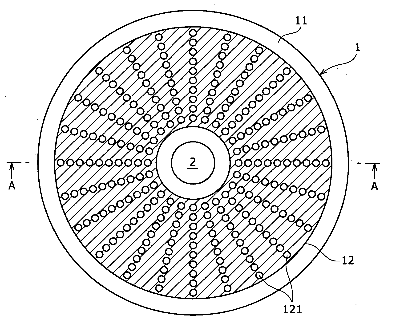
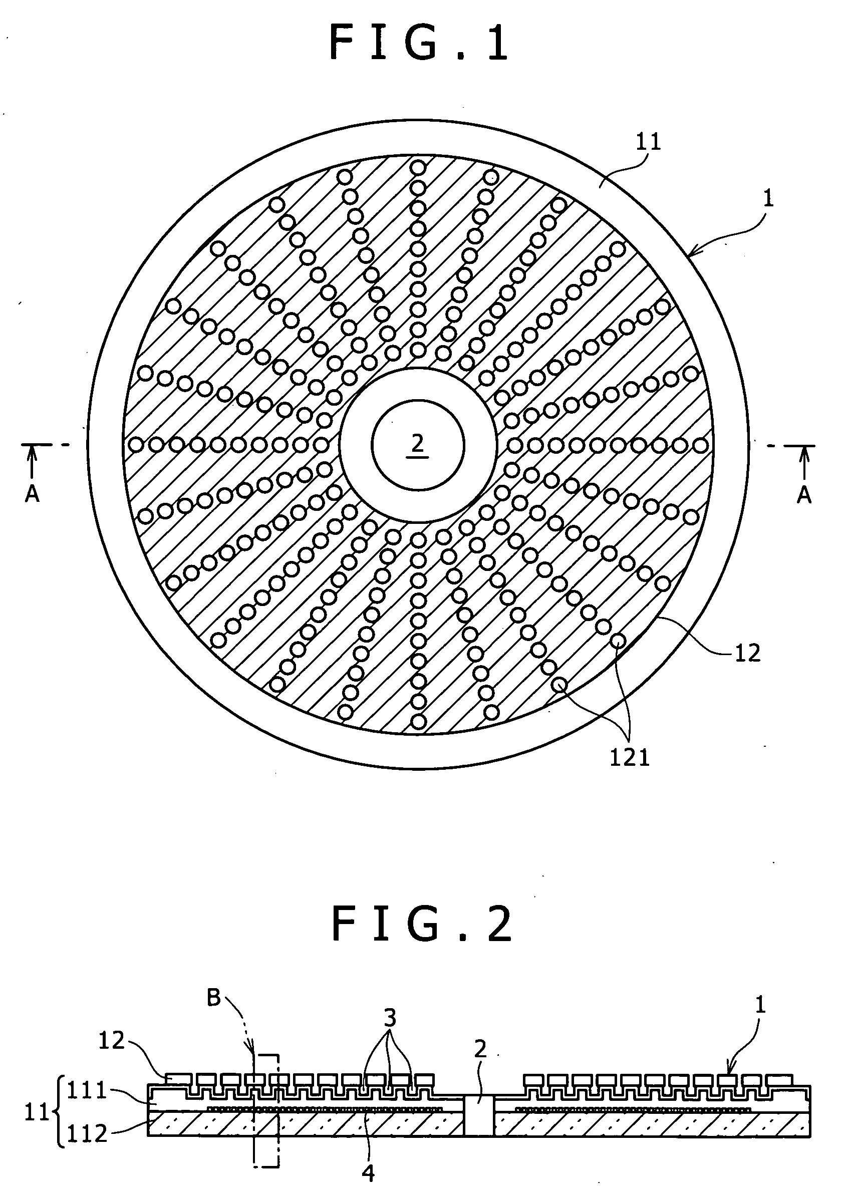
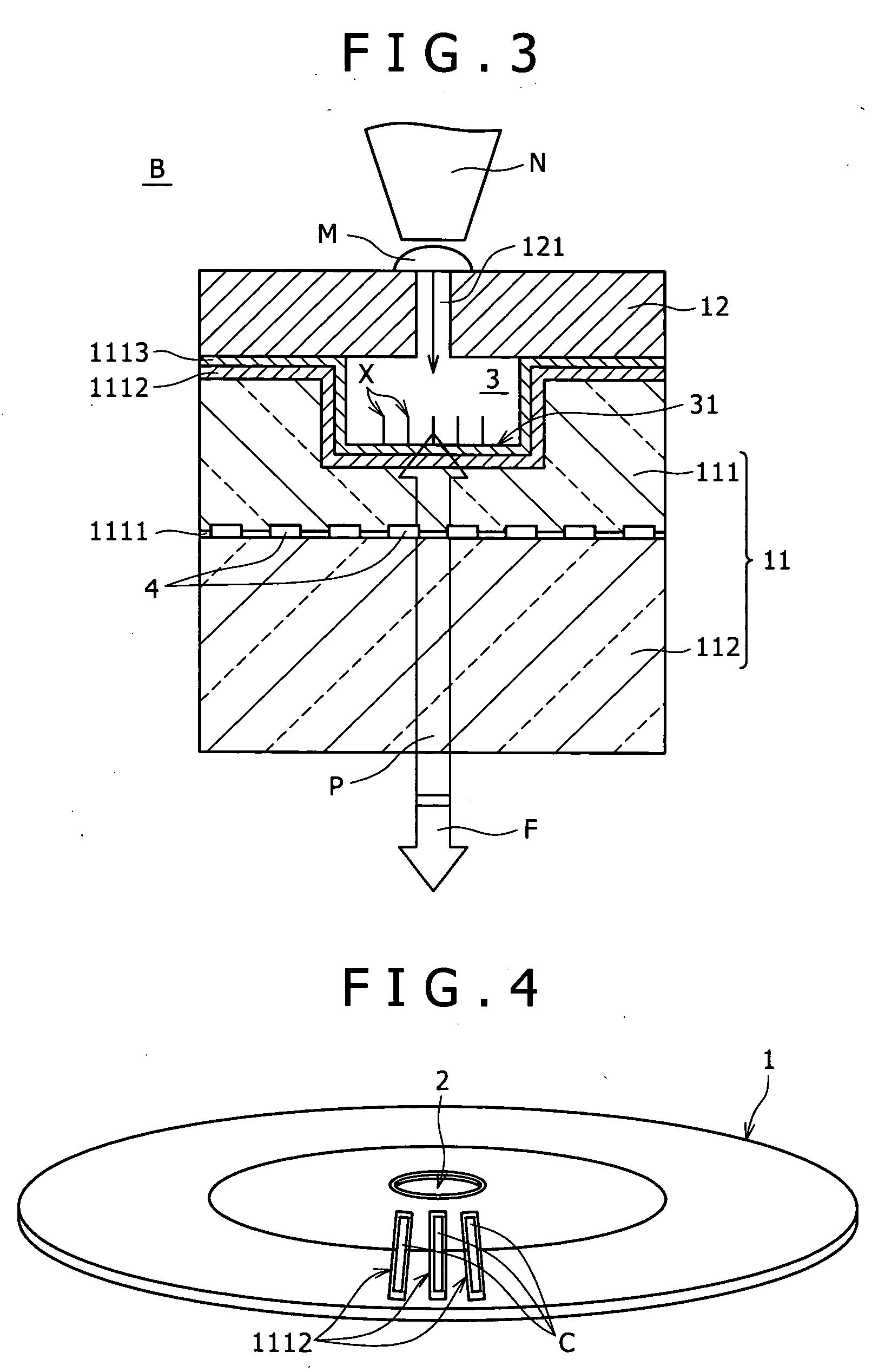
[0039]FIG. 1 is a plan view, as viewed from above, of a substrate for bioassay according to one embodiment of the invention. In FIG. 1, a substrate for bioassay indicated at 1 is one which is used to detect interaction between substances. The substrate is made of a disk-shaped plate similar to optical disks such as CD (compact disk), DVD (digital versatile disk) and the like. It is to be noted that although the substrate for bioassay of the invention is not limited to a disk-shaped form in a narrow sense, it is as a matter of fact that if it has a disk shape, apparatuses and techniques used for existing optical disks can be conveniently ...


PUM

PropertyMeasurementUnit
Electrical conductoraaaaaaaaaa
Transparencyaaaaaaaaaa
Fluorescenceaaaaaaaaaa

Abstract

A substrate for bioassay comprises a substrate and a group of reaction regions serving as a field where interaction between substances proceeds and formed in the substrate, and a group of information pits used to obtain positional information of individual reaction regions and / or substance information used in the reaction regions. The group of reaction regions and the group of information pits are not formed in the same substrate surface. A bioassay apparatus using the substrate and a method for making the substrate are also provided.

Description

CROSS REFERENCES TO RELATED APPLICATIONS [0001] The present invention contains subject matter related to Japanese Patent Application JP2005-146607 filed with the Japanese Patent Office on May 19, 2005, the entire contents of which being incorporated herein by reference. BACKGROUND OF THE INVENTION [0002] This invention relates to a technique related to a substrate for bioassay. More particularly, the invention relates to a substrate and device suited for bioassay for measuring and detecting interaction between substances and also to a method for making the substrate. [0003] At present, substrates that are called a DNA chip or DNA microarray (hereinafter referred generically to DNA chip) wherein a given DNA is (in full length or partly) microsequenced have been utilized for mutation evolution, SNP's (single nucleotide polymorphisms) analysis, a frequency analysis of genomic expression and the like and are now being used widely in other fields of drug discovery, clinical diagnosis, ph...

Claims


Application Information

Patent Timeline
IPC IPC(8): B01L9/00
CPCB01L3/5085B01L2300/02B01L2300/0645B01L2300/0806B01L2300/0887G01N2035/00772B01L2400/0415B29C45/263B29C45/372G01N33/553G01N35/00069B01L2300/168G01N33/53
Inventor TAKEDA, MINORUFURUKI, MOTOHIROITO, TATSUMI
Owner SONY CORP
Learn More