Micro power generator and apparatus for producing reciprocating movement

Inactive Publication Date: 2006-12-14
KOREA INST OF SCI & TECH
View PDF58 Cites 18 Cited by
  • Summary
  • Abstract
  • Description
  • Claims
  • Application Information

AI Technical Summary

Benefits of technology

[0006] Therefore, it is an object of the present invention to provide a micro power generator, which has enhanc

Problems solved by technology

However, such battery or fuel cell needs to be replaced with a new one after a predetermined period of time.
However, although various types of generators as mentioned above have been continuously developed and in

Method used


Image

  • Micro power generator and apparatus for producing reciprocating movement
  • Micro power generator and apparatus for producing reciprocating movement
  • Micro power generator and apparatus for producing reciprocating movement

Examples


Embodiment Construction

[0033] Preferred embodiments of the present invention will now be described in detail with reference to the accompanying drawings.

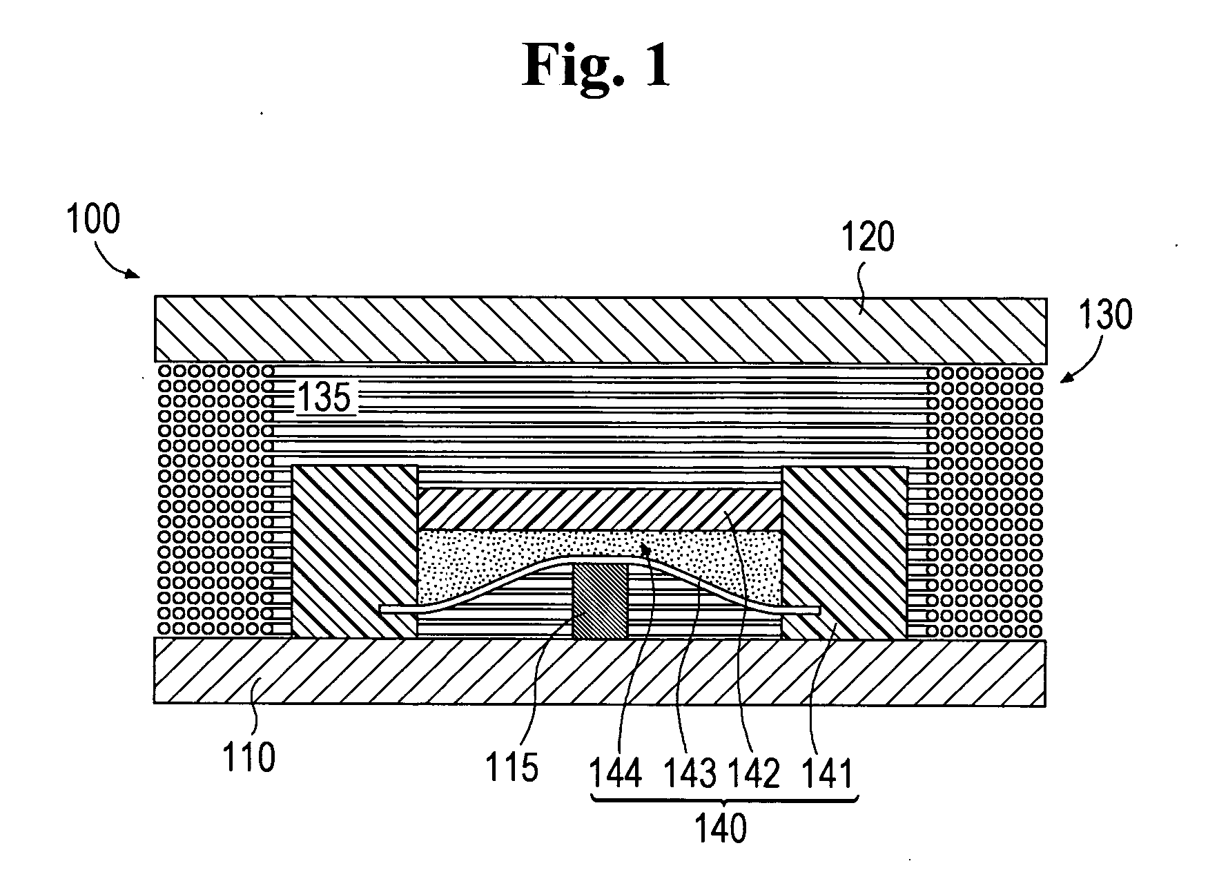
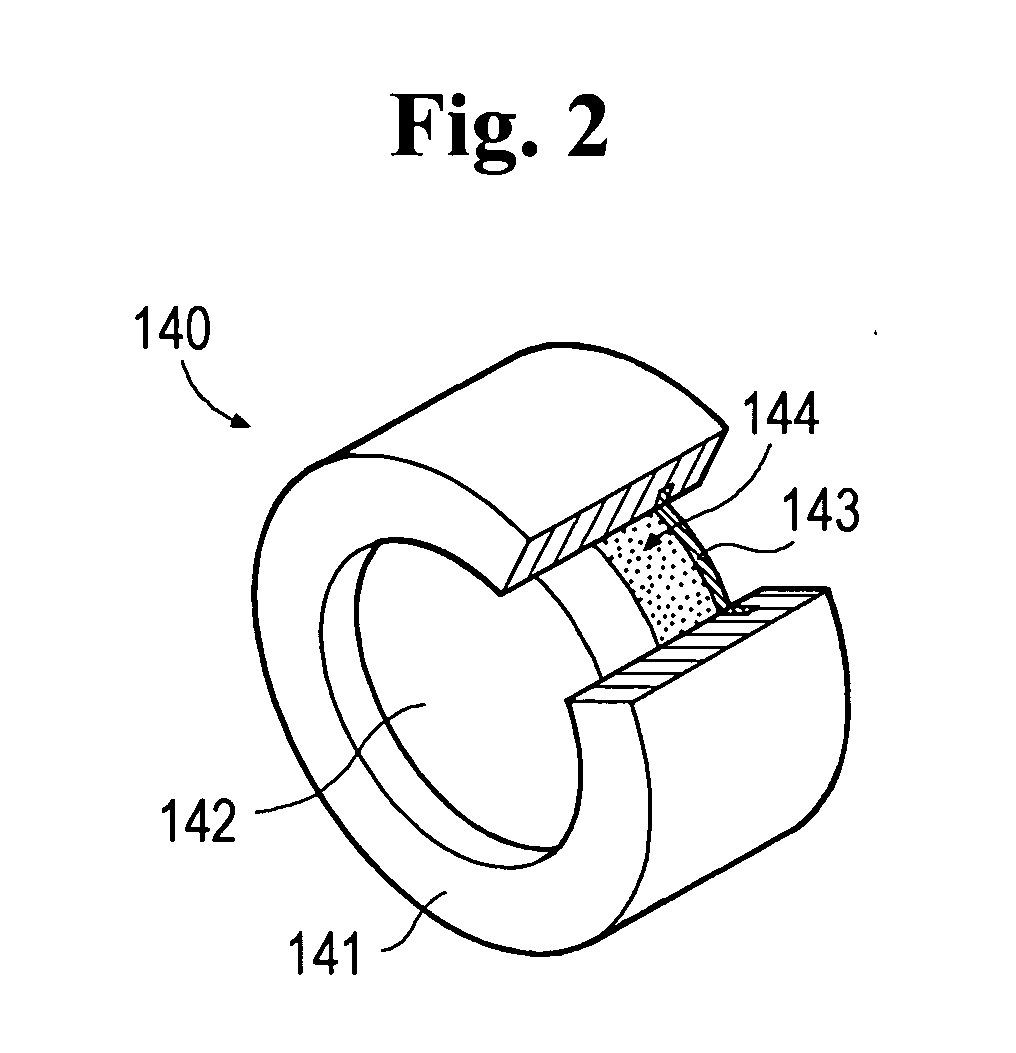
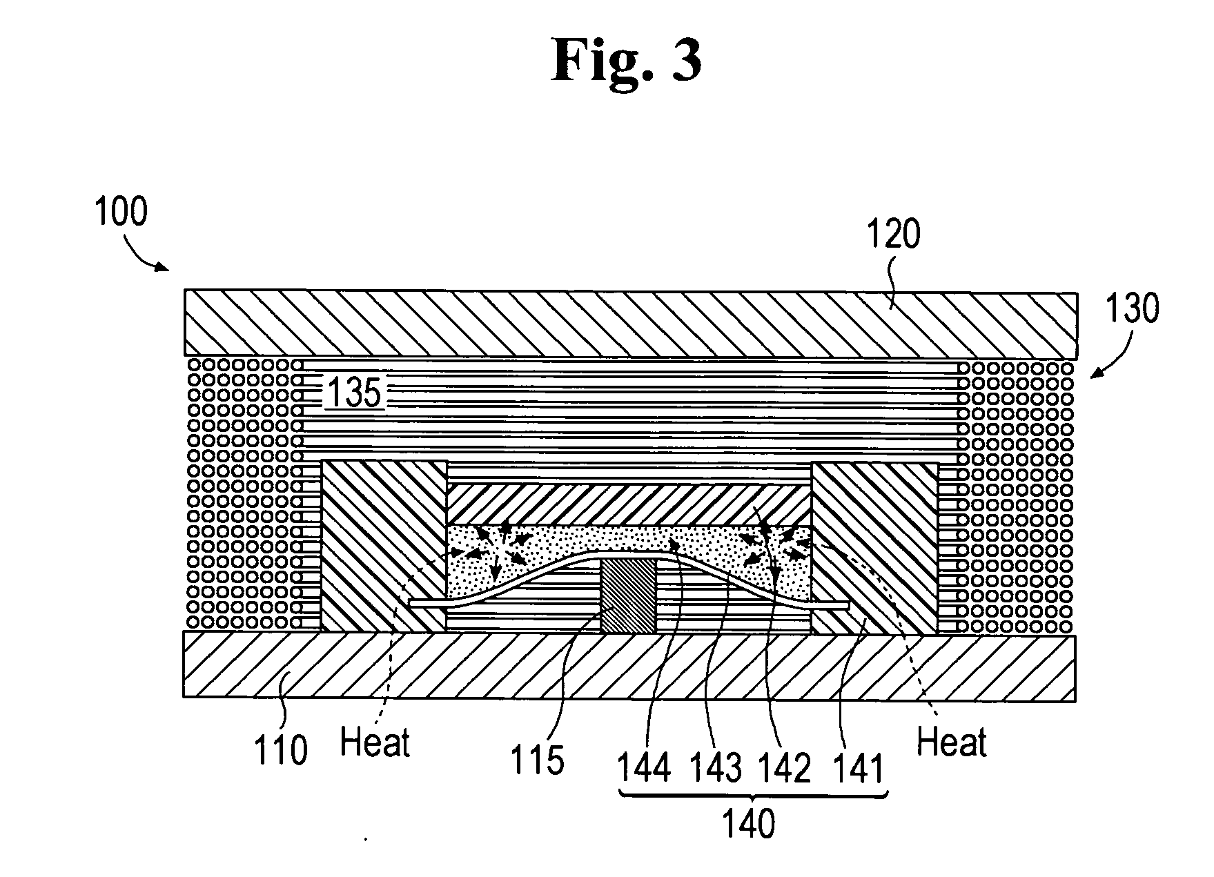
[0034]FIG. 1 is a sectional view illustrating a micro power generator constructed in accordance with a preferred embodiment of the present invention. FIG. 2 is a partially cut-away perspective view of an enclosed body shown in FIG. 1. FIG. 3 is a sectional view schematically illustrating a direction of heat transfer and a phase change of a working substance caused by the transferred heat. FIG. 4 is a sectional view illustrating a state wherein a permanent magnet is brought into contact with a low-temperature heat source side. In the above drawings, components are denoted by their corresponding reference numerals. It should be noted that the terms “high temperature” and “low temperature”, which are used herein to describe the present invention, do not mean a high temperature and a low temperature with respect to a certain absolute temperature. Rather, whe...


PUM


Abstract

There is provided a micro power generator enhanced in efficiency and power generation output, and having an increased temperature range for operation. The micro power generator comprises: a high-temperature heat source; a low-temperature heat source; an enclosed body containing a working substance therein, the enclosed body being deformable by means of a phase change of the working substance between a first shape wherein heat can be transferred from the high-temperature heat source and a second shape wherein heat can be transferred to the low-temperature heat source; a permanent magnet constituting the enclosed body, the permanent magnet being maintained in a first position when the enclosed body has the first shape and in a second position when the enclosed body has the second shape; and a wire in which an electric current is induced by a movement of the permanent magnet. Further, the present invention provides an apparatus for producing a reciprocating movement between two heat sources having a temperature difference therebetween.

Description

FIELD OF THE INVENTION [0001] The present invention generally relates to a micro power generator, and more particularly to a micro power generator adapted to convert thermal energy into electric energy in order to supply electrical power to a micro electro-mechanical system (hereinafter referred to as “MEMS”) and the like. Further, the present invention relates to an apparatus for producing reciprocable movement between two heat sources having a temperature difference therebetween. BACKGROUND OF THE INVENTION [0002] Generally, MEMS is provided with a plurality of components, which consume electrical power, such as a micro sensor, a micro actuator, a micro-pump, a microprocessor and the like. These components can be installed in a restricted space due to their micro-scale size. Although such components can be driven with a very small quantity of electrical power (compared to that of a macro system), it is necessary to supply a stable electrical power for reliable operations of the co...

Claims


Application Information

Patent Timeline
IPC IPC(8): H01L37/00
CPCB81B3/0024B81B2201/038H02K35/02F03G7/06H02K7/1876F01K25/08B81B7/02
Inventor KIM, KWANG HOSONG, GWI EUNJEON, JAE HAKLEE, YOON PYO
Owner KOREA INST OF SCI & TECH
Why Eureka
Try Eureka