
Microchannel cooling device with magnetocaloric pumping

Inactive Publication Date: 2006-12-14
IND TECH RES INST
View PDF9 Cites 52 Cited by
  • Summary
  • Abstract
  • Description
  • Claims
  • Application Information

AI Technical Summary

Benefits of technology

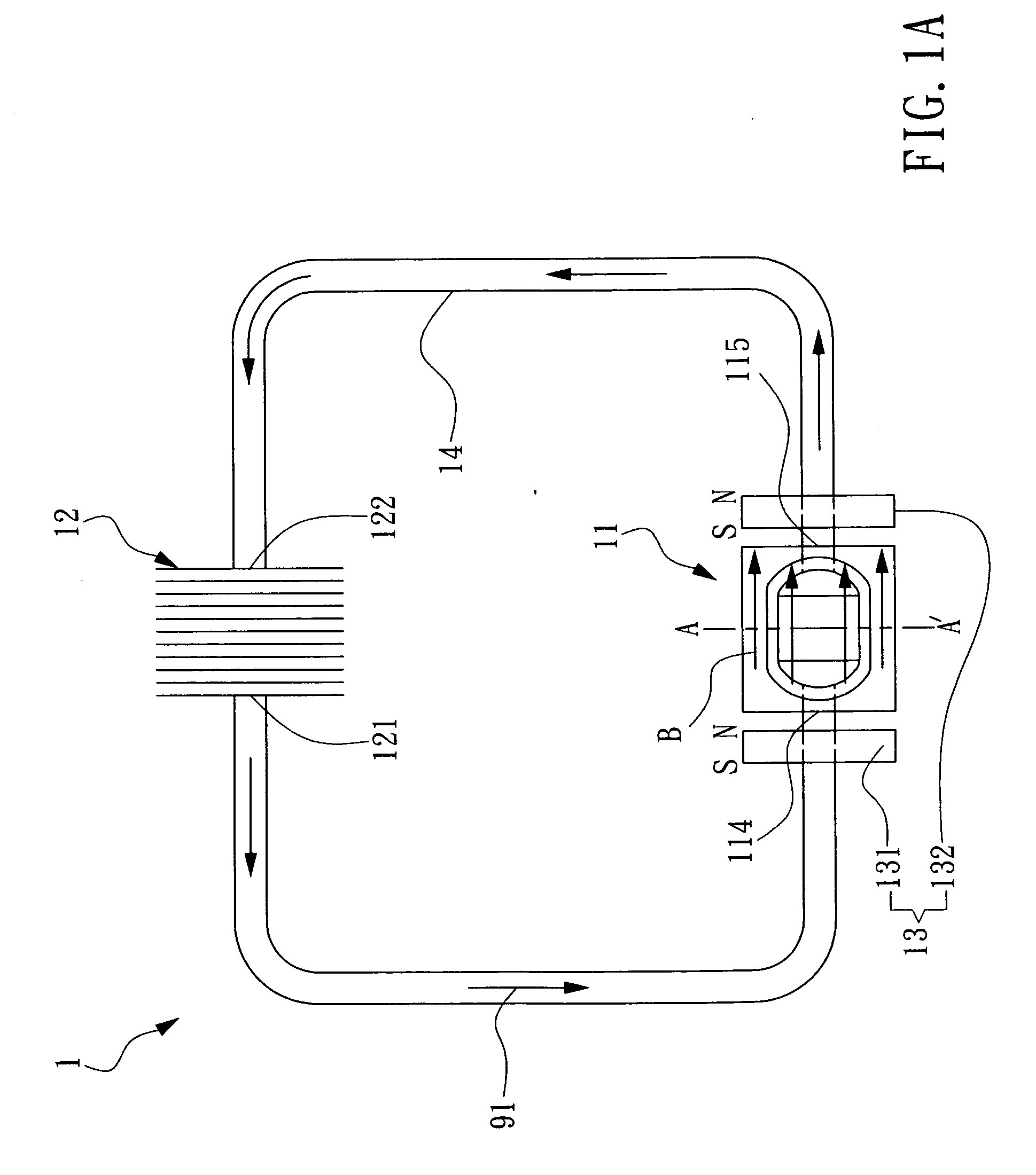
[0011] It is a further object of the invention to provide a microchannel cooling device, which can implement the nature circulation generated by loop thermosyphones to help increasing the flow speed of the ferrofluid flowing therein while consuming no additional power.

Problems solved by technology

As the number of transistors on a single chip has grown 300 million-fold since Intel introduced its first microprocessor 35 years ago that represents a performance increase of about 80 percent per year, the cramping of transistors on a chip of limited area has brought the heat dissipation issue to become a challenge for continuing the aforesaid progress as predicted by Moore's Law.
No matter it is a personal computer or a notebook computer, both are troubled by the same heat dissipation problem.
Even with cooling fans installed in the both, not to mention that the heat dissipating efficiency of the cooling fan is questionable, the increasing of power consumption and overall weight will be the additional problems requiring to be addressed.
As transistors get smaller, heat dissipation issues develop.
As the performance of CPU is increasing while generating more heat to be dissipated, the conventional heat dissipation technology for electronic devices, i.e. fan thermal module, is no longer capable of meeting the requirement of the future high performance CPUs.
However, a pump is required in the liquid cooling system for driving coolant to circulate therein, which can be as bulky as the size of 100×50×86 mm for example and is very noisy while operating.
Moreover, the heat transfer efficiency of a liquid cooling system might be limited, since heat transfer can only occur at the boundary layer close to the wall of the tube containing the coolant of the liquid cooling system whereas the majority of the coolant is flowing at the proximity of the center of the tube.
Nevertheless, although the referring loop thermosyphon system is capable of cooling down the temperature of a microprocessor, the dimension of the microchannel used in the invention is still too large such that its heat transfer coefficient is not satisfactory.
Although the aforesaid liquid cooling system is efficient in heat dissipation, it is adversely affected by its power consumption since it is required to provide electrical current to the magnetic pump for enabling the same to operate.

Method used


Image

  • Microchannel cooling device with magnetocaloric pumping
  • Microchannel cooling device with magnetocaloric pumping
  • Microchannel cooling device with magnetocaloric pumping

Examples


first embodiment

[0039] Please refer to FIG. 2, which is a schematic diagram showing a second preferred embodiment of the invention. The microchannel cooling device 2 of this preferred embodiment is substantially a two-phase microchannel cooling device with loop thermosyphones circulation and magnetocaloric pumping, which comprises a heat sink 21, a condenser 22 and a magnetocaloric pump 23. The detail structure of the heat sink 21, the condenser 22 and the magnetocaloric pump 23 are the same as that of the invention and thus will not be described further hereinafter. The microchannel cooling device 2 further comprises: a two-phase conduit 25 for connecting the outlet 215 of the heat sink 21 to the inlet 222 of the condenser 22; and a conduit 24 with pure liquid flowing therein for connecting the outlet 221 of the condenser 22 to the inlet 214 of the heat sink 21. It is noted that the mixture of vapor-phase and liquid-phase ferrofluid 92 is flowing in the two-phase conduit 25 while only the liquid-s...

third embodiment

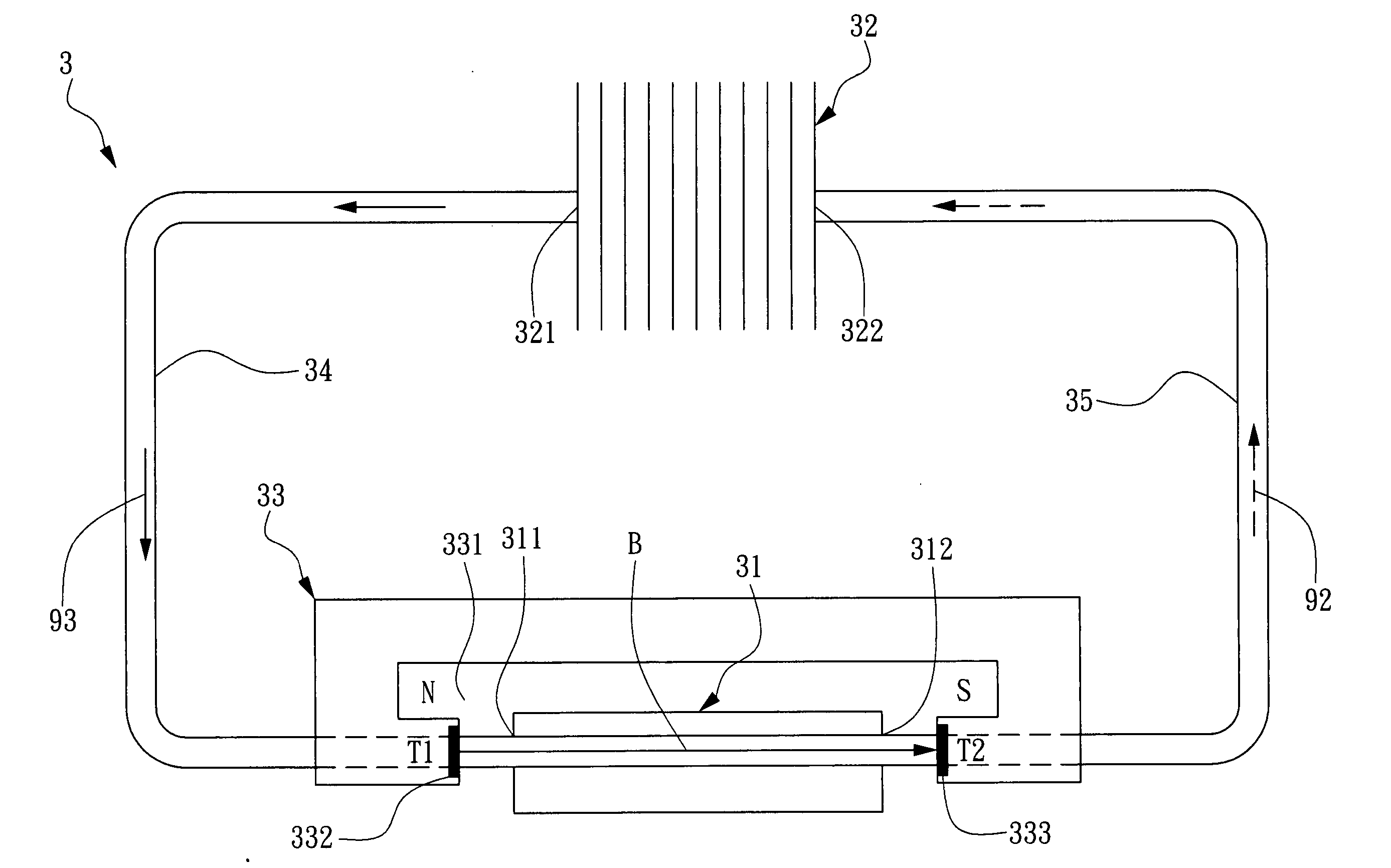
[0041] The second and the invention is designed for the purpose of improving the flowing efficiency of ferrofluid. Thus, by selecting a proper ferrofluid, the heated ferrofluid is vaporized to generate the thermosyphone effect so that the vapor-state and the liquid-state ferrofluid co-exist in the circulation and thus the flow speed of the ferrofluid is increased. In these embodiments, the major circulation is relied on loop thermosyphon, the magnetocaloric pump is for overcoming the friction and pressure loss exerting on the ferrofluid by each microchannel.

[0042] The operation principle of the second and the third embodiment of the invention is illustrated in FIG. 2 and FIG. 5, which are schematic diagrams depicting a two-phase circulation of the third preferred embodiment of the invention. The heat sink 31, having a plurality of microchannels embedded thereon for receiving a ferrofluid 93 to flow therein, is disposed on an electronic device 4 (e.g. a CPU) for absorbing heat genera...


PUM


Abstract

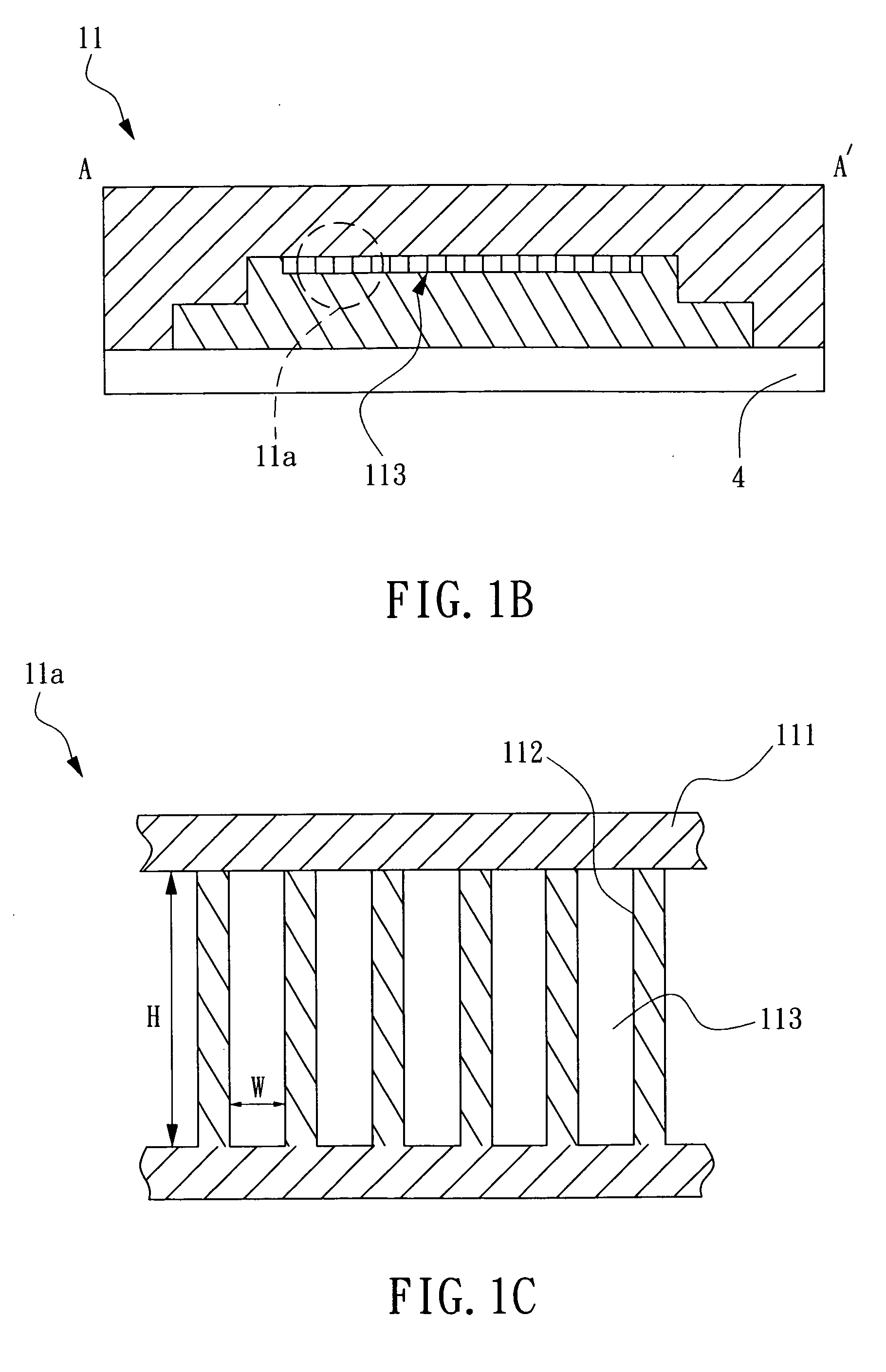
The invention discloses a microchannel cooling device, adapted for dissipating heat generated from an electronic device, which comprises: a heat sink, being arranged on the electronic device and having an inlet, an outlet and a plurality of microchannels embedded thereon for receiving a ferrofluid to flow therein; a condenser, having an outlet connected to the inlet of the heat sink and an inlet connected to the outlet of the heat sink; and a magnetocaloric pump, for providing a magnetic field to the ferrofluid flowing in the heat sink; wherein the magnetocaloric effect (MCE) caused by the working of the magnetic field on the ferrofluid flowing in the heat sink is used for driving the ferrofluid to flow through the plural microchannels of the heat sink while absorbing heat therefrom, and thereafter, the heated ferrofluid flow into the condenser for discharging heat and then the cool-down ferrofluid is guided back to the heat sink to complete a circulation. The invention make use of the high heat transfer performance of the plural microchannels, the nature circulation caused by the loop thermosyphone and the driving of the magnetocaloric pump so as to constitute a cooling device with no mechanically moving elements.

Description

FIELD OF THE INVENTION [0001] The present invention relates to a microchannel cooling device, and more particularly, to a microchannel cooling device utilizing a magnetocaloric pump for driving a ferrofluid flowing therein to form a heat-dissipating circulation. BACKGROUND OF THE INVENTION [0002] In 1965, Gordon Moore, Director of Fairchild Semiconductor's Research and Development Laboratories, wrote an article on the future development of semiconductor industry for the 35th anniversary issue of Electronics magazine. In the article, Moore noted that the complexity of minimum cost semiconductor components had doubled per year since the first prototype microchip was produced in 1959. This exponential increase in the number of components on a chip became later known as Moore's Law. In the recent decade, as predicted by the Moore's Law, the manufacturing process of semiconductor had progressed from the 0.7 mm process with 100K transistors on an integrated circuit of fixed size at 1989 t...

Claims


Application Information

Patent Timeline
IPC IPC(8): H05K7/20F28D15/00H02K44/00
CPCF25B2321/0021H01L23/473H02K44/06H01L2924/0002H01L2924/00
Inventor HSU, LI-CHIEH
Owner IND TECH RES INST
Learn More