
Three-dimensional balun

Active Publication Date: 2006-12-14
NAT TAIWAN UNIV
View PDF4 Cites 12 Cited by
  • Summary
  • Abstract
  • Description
  • Claims
  • Application Information

AI Technical Summary

Benefits of technology

[0010] The secondary objective of the invention is to provide a three-dimensional balun that is capable of using multiple transmission lines to construct a vertical circuit to reduce the circuit space requirements for the miniature integrated circuits.
[0011] The tertiary objective of the invention is to provide a three-dimensional balun using low-temperature co-fired ceramic technology or FR4 substrates, so as to reduce the production costs and facilitates batch production of the miniature integrated circuits.

Problems solved by technology

An active type balun that incorporates a pre-amplifier is able to provide broad bandwidth and high gain, but often accompanied by high spurious output level and extra power consumption.
A lumped type balun, though saves on circuit space employing lumped inductors and capacitors, is limited in bandwidth and can only support below 10 GHz.
However, the Marchand and rat-race baluns have to use quarter-wavelength transmission lines, thus taking up more circuit space.

Method used


Image

  • Three-dimensional balun
  • Three-dimensional balun
  • Three-dimensional balun

Examples


Embodiment Construction

[0020] The more important features of the invention have thus been outlined, rather broadly, so that the detailed description thereof that follows may be better understood, and in order that the present contribution to the art may be better appreciated.

[0021] Additional features of the invention will be described hereinafter, which will form the subject matter of the claims appended hereto.

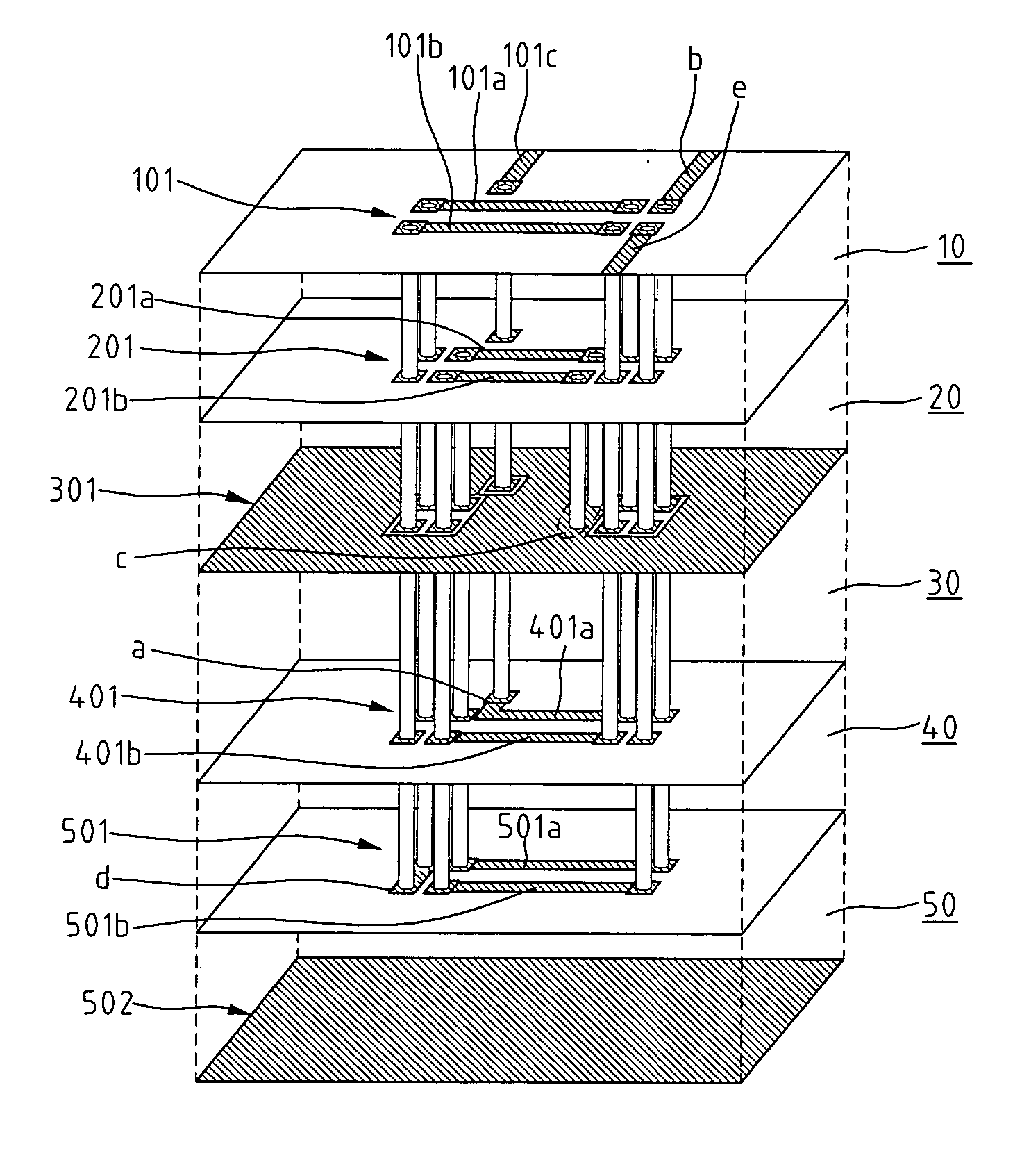
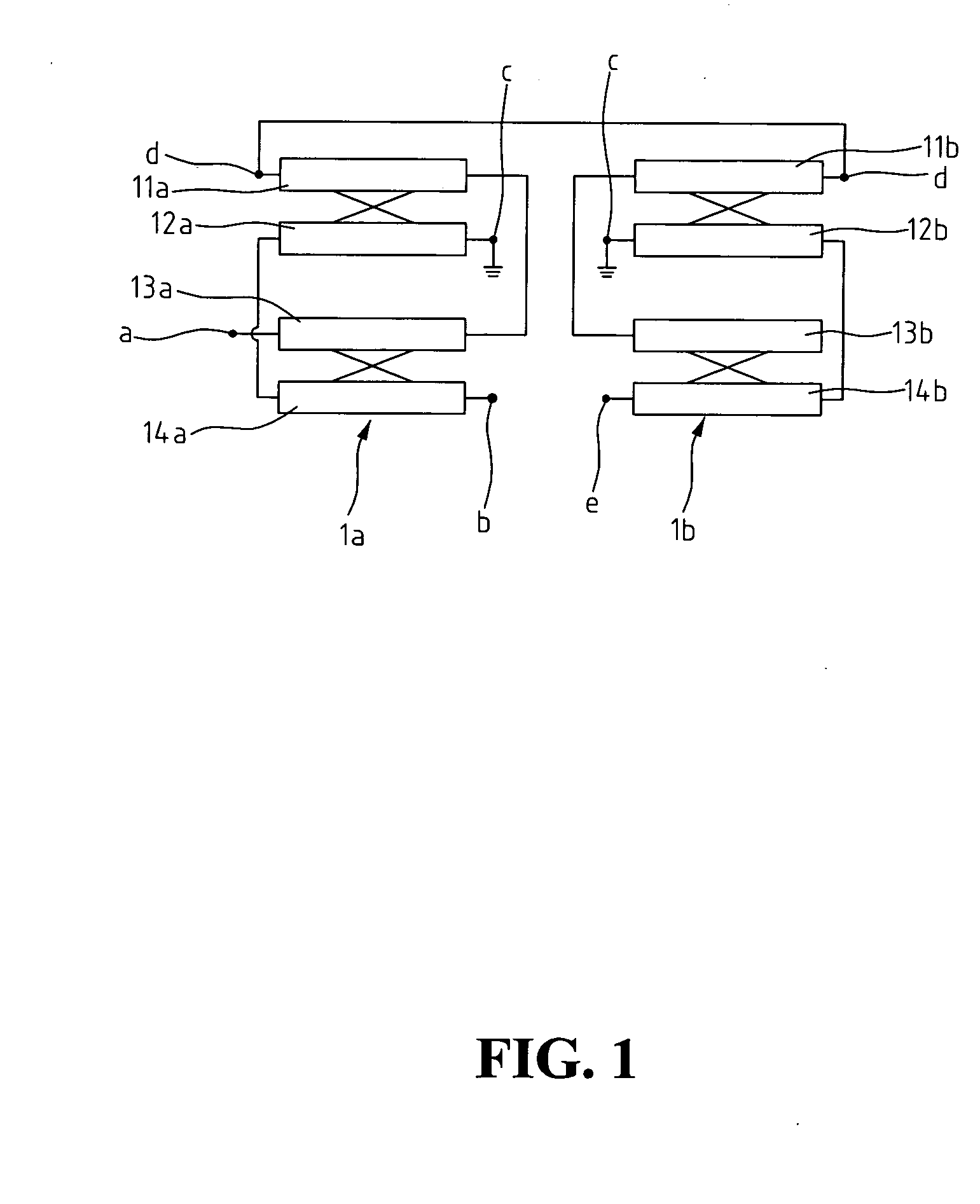
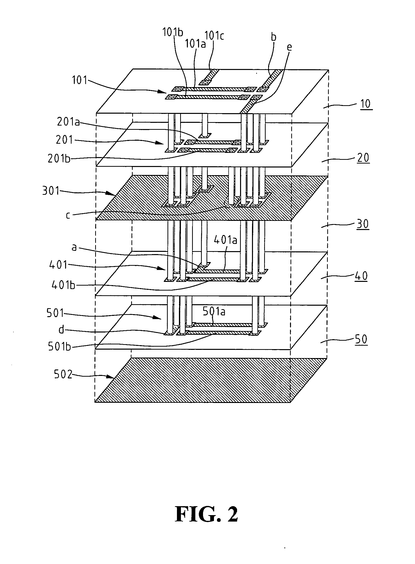
[0022] Referring to FIG. 1, the three-dimensional balun is a multi-layer circuit structure, which corresponds to an equivalent circuit shown in FIG. 1 having two matching coupled lines: a first coupling component 1a and a second coupling component 1b. The first coupling component 1a includes multiple transmission lines: a transmission line 11a, a transmission line 12a, a transmission line 13a, and a transmission line 14a; and the second coupling component 1b includes multiple transmission lines: a transmission line 11b, a transmission line 12b, a transmission line 13b, and a transmission line 14...


PUM


Abstract

A three-dimensional balun is disclosed by laminating alternate layers of conductor and dielectric substrate on top of each other to create a microwave circuit. The laminated layers are constructed in a transmission line configuration, corresponding to an equivalent circuit, wherein the first and third transmission lines, the fifth and seventh transmission lines, the second and fourth transmission lines, and the sixth and eighth transmission lines are pairs of coupling lines; one end of the sixth transmission line is defined as an input; one end of the seventh transmission line is defined as a first output; one end of the eighth transmission line is defined as a second output. When signals close to the center frequency of the operating balun are input from the unbalanced side, the signals are converted and then output through the first and second outputs having the same amplitude and producing 180-degree phase shifts.

Description

BACKGROUND OF THE INVENTION [0001] 1. Field of the Invention [0002] The present invention relates to a three-dimensional balun, and in particular to a multi-layer microwave circuit that is implemented in high density microwave integrated circuits for linking an unbalanced circuit to a balanced circuit or vice versa. [0003] 2. The Related Art [0004] Conventional microwave circuits or balanced-unbalanced converters are often referred to as baluns, commonly used in mixers, push-pull amplifiers, and voltage-controlled oscillators, and phase shifters, and antennas. A typical balun converts balanced signals to unbalanced signals, or from unbalanced signals to balanced signals in microwave or milliwave transmissions.[0005] For instance, when signals close to the center frequency of the operating balun are input from the unbalanced side, the signals are converted and then output through two outputs having the same amplitude and producing 180-degree phase shifts. [0006] The baluns can be dis...

Claims


Application Information

Patent Timeline
IPC IPC(8): H01P5/10
CPCH01P5/10
Inventor WU, PEI-SIHUANG, TIAN-WEIWANG, HUEI
Owner NAT TAIWAN UNIV
Features
  • Generate Ideas
  • Intellectual Property
  • Life Sciences
  • Materials
  • Tech Scout
  • Unparalleled Data Quality
  • Higher Quality Content
  • 60% Fewer Hallucinations
Learn More