
Basestation methods and apparatus for supporting timing synchronization

a technology of basestation and timing synchronization, which is applied in the direction of synchronisation arrangement, data switching network, wireless commuication services, etc., can solve the problems of difficult or impractical deployment and maintenance of terrestrial base stations, “dead zones”, and inability to deploy permanent terrestrial base stations. achieve the effect of increasing the average transmit power, improving the probability of clipping, and improving the transmission power

Active Publication Date: 2006-12-14
QUALCOMM INC
View PDF22 Cites 41 Cited by
  • Summary
  • Abstract
  • Description
  • Claims
  • Application Information

AI Technical Summary

Benefits of technology

The present invention is about improving synchronization in communication systems with remote base stations and large coverage areas. The invention provides methods and apparatus for synchronizing uplink transmission timing of a communications device with a base station, even if the device is not synchronized with the base station in terms of uplink transmission timing. The invention allows for access intervals to occur at periodic intervals during which communications devices can make access requests. The invention also allows for the use of beacon signals and the measurement of signals in terms of downlink timing to control uplink transmission timing. The invention can be used in both terrestrial and satellite base station systems and supports high data rates and low peak to average power ratio.

Problems solved by technology

While terrestrial base stations are useful in areas where the population is sufficient to justify the cost of a terrestrial base station, in many locations on the planet there is insufficient commercial justification to deploy a base station and / or due to geographic issues it is impractical to deploy a permanent terrestrial base station.
For example, in physically inhospitable areas such as the open ocean, dessert regions and / or regions which are covered by ice sheets it may be difficult or impractical to deploy and maintain a terrestrial base station.
The lack of base stations in some geographic regions leads to “dead zones” in which is not possible to communicate using a cell phone.
Satellite base stations are extremely costly to deploy given the cost of launching satellites.
In addition, there is limited space above the planet in which geostationary satellites can be placed.
While satellites in geostationary orbit have the advantage of being in a fixed position relative to the earth, lower earth orbiting satellites can also be deployed but such satellites remain costly to deploy and will remain in orbit for a shorter period of time due to their initially lower orbit than a geostationary satellite.
Unfortunately, the distances which signals must travel in the case of satellite base stations is considerable longer than the distance signals normally travel to reach a conventional terrestrial base station which is usually a few miles at most.
As a result, most satellite phones normally are relatively large and bulky compared to conventional cell phones due to the size of the batteries, power amplifiers and other circuitry which has been used to implement cell phones.
The need for a relatively large, and therefore often bulky, power amplifier results, in part, from the fact that many conventional communications systems have a less than ideal peak to average power ratio.
Given the large distance to a satellite base station and / or comparatively large cell size, as compared to a terrestrial base station, uplink timing synchronization used for terrestrial base stations which use OFDM signals in the uplink may not be sufficient to achieve adequate uplink symbol timing synchronization when communicating with a satellite base station.

Method used


Image

  • Basestation methods and apparatus for supporting timing synchronization
  • Basestation methods and apparatus for supporting timing synchronization
  • Basestation methods and apparatus for supporting timing synchronization

Examples


Embodiment Construction

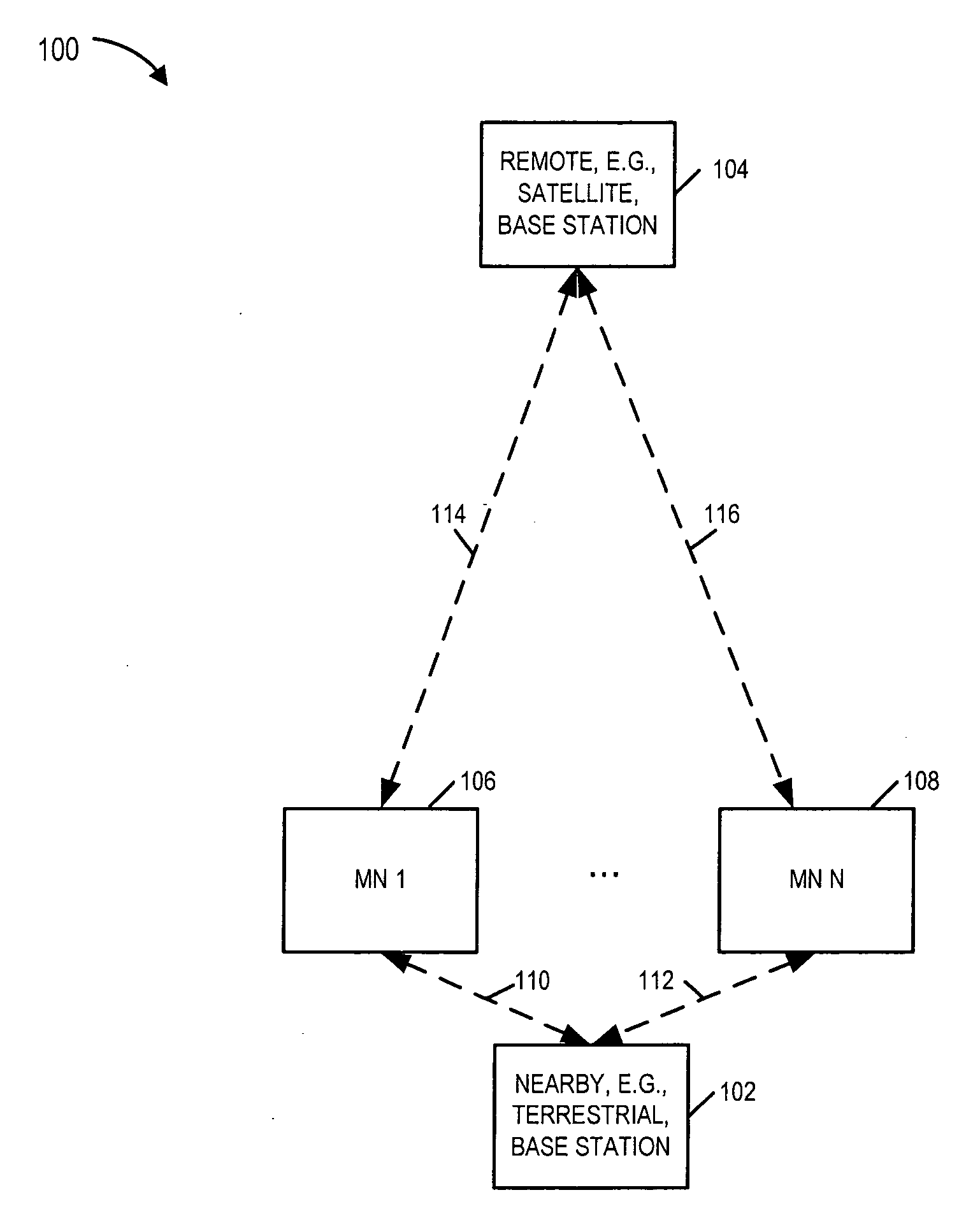
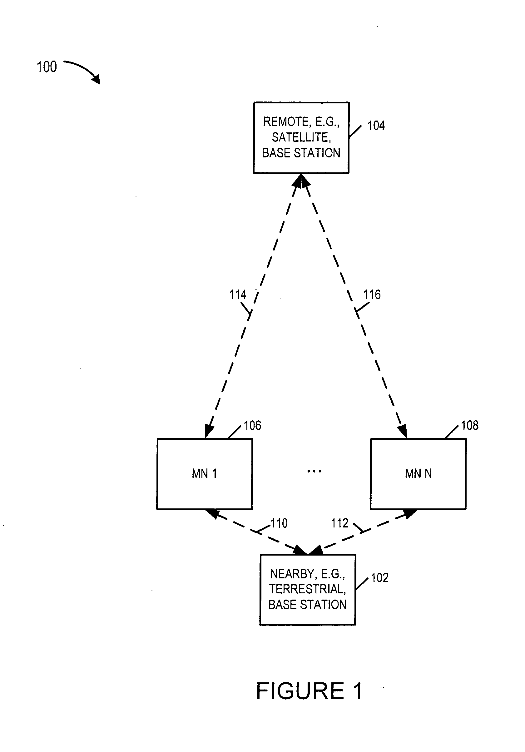
[0059]FIG. 1 is a drawing of an exemplary wireless communications system 100 implemented in accordance with the present invention and using methods of the present invention. The exemplary system 100 is an exemplary Orthogonal Frequency Division Multiplexing (OFDM) multiple access spread spectrum wireless communications system. The exemplary system 100 includes a plurality of base stations (102, 104) and a plurality of wireless terminals (106, 108), e.g., mobile nodes. The various base stations (102, 104) may be coupled together via a backhaul network. The mobile nodes (MN1106, MN N 108) may move throughout the system and use a base station, in whose coverage area it is currently located, as it point of network attachment. Some of the base stations are terrestrial based base stations, e.g., BS 102, and some of the base stations are satellite based base stations, e.g., BS 104. From the perspective of the MNs (106, 108), the terrestrial base stations are considered nearby base stations...


PUM


Abstract

A wireless terminal using OFDM signaling supporting both terrestrial and satellite base station connectivity operates using conventional access probe signaling in a first mode of operation to establish a timing synchronized wireless link with a terrestrial base station. In a second mode of operation, used to establish a timing synchronized wireless link with a satellite base station, a slightly modified access protocol is employed. The round trip signaling time and timing ambiguity between a wireless terminal and a satellite base station is substantially greater than with a terrestrial base station. The modified access protocol uses coding of access probe signals to uniquely identify a superslot index within a beaconslot. The modified protocol uses multiple access probes with different timing offsets to further resolve timing ambiguity and allows the satellite base station access monitoring interval to remain small in duration. Terrestrial base station location / connection information is used to estimate initial timing.

Description

RELATED APPLICATIONS [0001] The present application claims the benefit of U.S. Provisional Patent Application Ser. No. 60 / 689,910, filed on Jun. 13, 2005, titled “METHODS AND APPARATUS FOR SUPPORTING OFDM UPLINKS WITH REMOTE BASE STATIONS”, which is hereby expressly incorporated by reference.FIELD OF THE INVENTION [0002] The present application is directed to methods and apparatus which can be used in implementing an OFDM system which uses OFDM tones for communicating uplink signals to terrestrial and / or satellite base stations. BACKGROUND [0003] The ability to communicate using a handheld communications device, e.g., a portable telephone, regardless of one's location in a wide area is of great value. The value of such a device is important to military applications as well as in the case of conventional consumer based applications. [0004] Terrestrial base stations have been installed at various earth based locations to support voice and / or data services. Such base stations normally ...

Claims


Application Information

Patent Timeline
Patent Type & Authority Applications(United States)
IPC IPC(8): H04L12/43H04W56/00
CPCH04W56/0045H04B7/2125H04L7/00H04B7/155H04B7/185
Inventor LANE, FRANK A.LAROIA, RAJIVLI, JUNYI
Owner QUALCOMM INC
Learn More