Screw compressor

a compressor and screw technology, applied in the direction of machines/engines, liquid fuel engines, positive displacement liquid engines, etc., can solve the problems of increased cost of gears or motors, sometimes difficult manufacturing facilities, and increase in manufacturing costs, so as to reduce the cost and reduce the rotation speed

Active Publication Date: 2006-12-14
HITACHI IND EQUIP SYST CO LTD
View PDF21 Cites 29 Cited by
  • Summary
  • Abstract
  • Description
  • Claims
  • Application Information

AI Technical Summary

Benefits of technology

[0042] According to the invention, it is possible to make a motor relatively low in rotating speed

Problems solved by technology

In the case where the gear is to be made large in diameter, manufacture becomes sometimes difficult in terms of a manufacturing facilit

Method used


Image

  • Screw compressor
  • Screw compressor
  • Screw compressor

Examples


first embodiment

[0056] the invention will be described with reference to FIGS. 1 to 5.

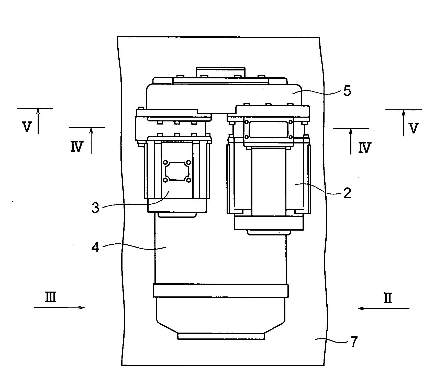
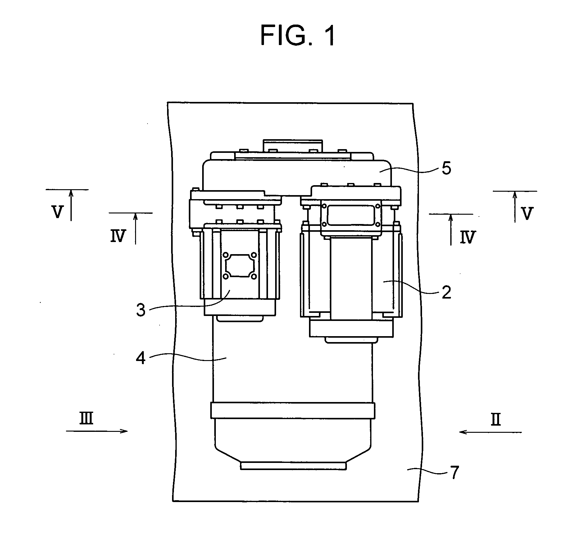
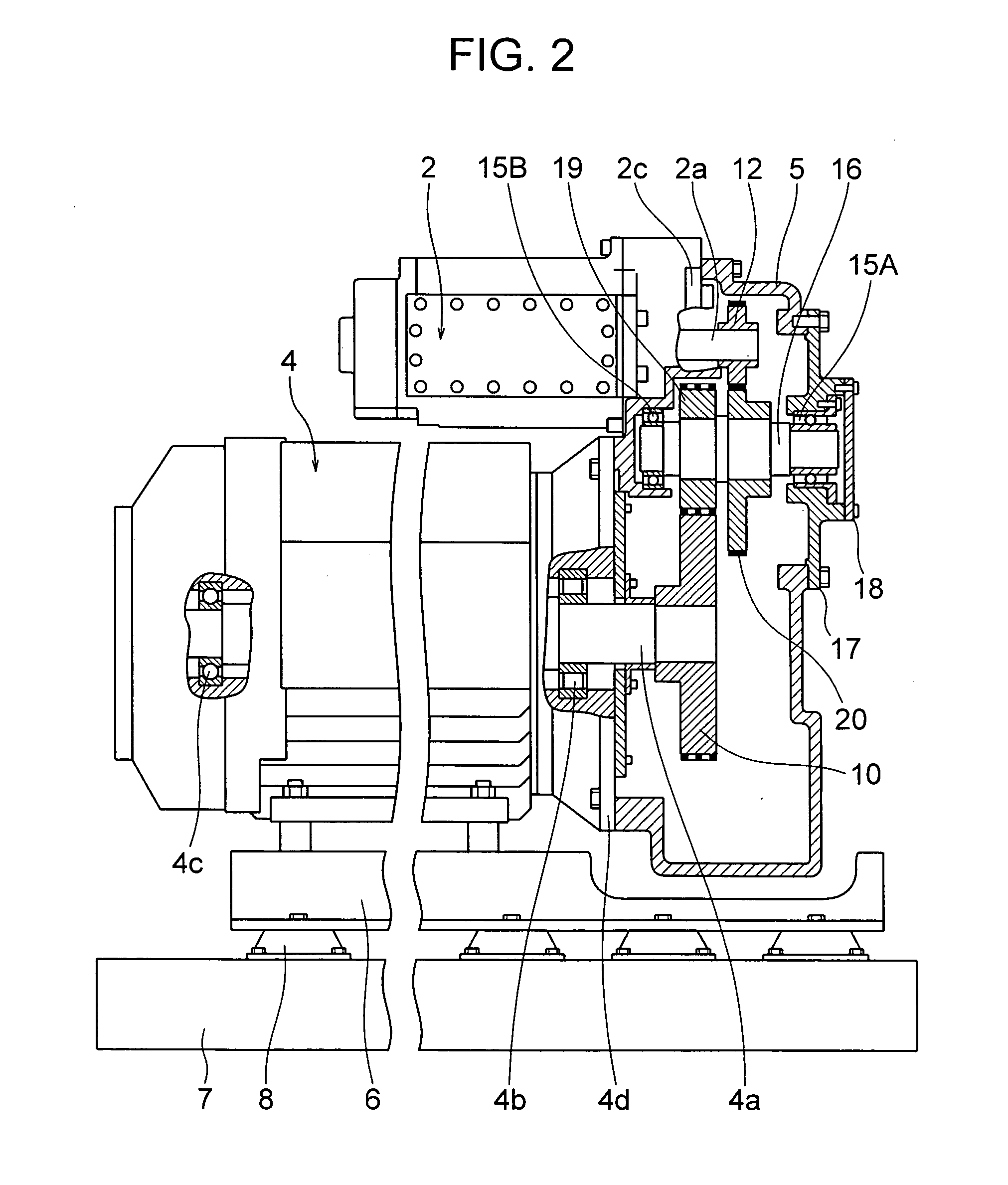
[0057]FIG. 1 is a plan view showing the construction of a screw compressor according to the embodiment. FIG. 2 is a side view as viewed in a direction indicated by an arrow II in FIG. 1. FIG. 3 is a side view as viewed in a direction indicated by an arrow III in FIG. 1. FIG. 4 is a side, cross sectional view taken along a cross section IV-IV in FIG. 1, and FIG. 5 is a side, cross sectional view taken along a cross section V-V in FIG. 1 (only an interior of a casing is shown).

[0058] In FIGS. 1 to 5, there are provided: a low pressure stage compressor body 2 that compresses an air, which is sucked thereinto through a suction throttle valve 1 (not shown in the drawings , but see the drawings illustrated later), to a predetermined intermediate pressure; a high pressure stage compressor body 3 that compresses the compressed air, which has been compressed by the low pressure stage compressor body 2, further to a predet...


PUM


Abstract

A screw compressor comprising: a low pressure stage compressor body; a high pressure stage compressor body that further compresses a compressed air compressed by the low pressure stage compressor body; pinion gears for example, respectively, provided on, for example, a male rotor of the low pressure stage compressor body and, for example, a male rotor of the high pressure stage compressor body; a motor; a bull gear for example, provided on a rotating shaft of the motor; and an intermediate shaft supported rotatably and provided with a pinion gear, which meshes with the bull gear, and a bull gear, which meshes with the pinion gears. Thereby, it is possible to make the motor relatively low in rotating speed while inhibiting the gears from being increased in diameter, thus enabling achieving reduction in cost.

Description

INCORPORATION BY REFERENCE [0001] The present application claims priority from Japanese application JP2005-169661 filed on Jun. 9, 2005, the content of which is hereby incorporated by reference into this application. BACKGROUND OF THE INVENTION [0002] The present invention relates to a screw compressor, and more particular, to a large capacity screw compressor that generates a compressed air. [0003] Screw compressors comprise a male rotor and a female rotor, of which rotating shafts are in parallel to each other and which rotate so that spiral teeth thereof mesh with each other, and a casing that accommodates therein the male rotor and the female rotor. A plurality of compressive working chambers are defined by tooth grooves of the male rotor and the female rotor, and an inner wall of the casing. The compressive working chambers are decreased in volume to compress an air while moving in an axial direction as the male rotor and the female rotor rotate. [0004] Conventionally, the cons...

Claims


Application Information

Patent Timeline
IPC IPC(8): F04B17/00
CPCF01C21/007F04C18/16F04C29/04F04C23/001F04C29/005F04C23/00
Inventor NISHIMURA, HITOSHISUZUKI, TOMOOOHTA, HIROSHI
Owner HITACHI IND EQUIP SYST CO LTD
Why Eureka
Try Eureka