Differential unit with limited slip differential mechanism

a technology of differential mechanism and differential unit, which is applied in mechanical actuated clutches, gearing, transportation and packaging, etc., can solve the problem of not being able to sufficiently limit the differential action of the planetary gear mechanism, and achieve the effect of reducing manufacturing costs, simple structure and easy manufacturing and assembly

Inactive Publication Date: 2006-12-14
SUBARU CORP
View PDF8 Cites 20 Cited by
  • Summary
  • Abstract
  • Description
  • Claims
  • Application Information

AI Technical Summary

Benefits of technology

[0009] An object of the present invention is to provide a differential unit with a limited slip differential mechanism that a clutch plate can be positioned and fixed to a planetary carrier with simple structure, that is easy to manufacture and assemble, and can achieve reduced manufacturing cost.
[0011] According to the present invention, it can be handled simply with normal components provided in the planetary carrier and only processing areas provided on clutch plate side, which means that there is no need for dedicated components or special processes, and it is possible to position and fix the clutch plate to the planetary carrier easily, manufacture and assembly are simplified, and it is possible to reduce manufacturing costs.

Problems solved by technology

But the clutch plate is provided between the planetary carrier and the other clutch plate, the clutch plate and the planetary carrier are rotated relative to each other, it is not possible to sufficiently limit differential action of the planetary gear mechanism.

Method used


Image

  • Differential unit with limited slip differential mechanism
  • Differential unit with limited slip differential mechanism
  • Differential unit with limited slip differential mechanism

Examples


first embodiment

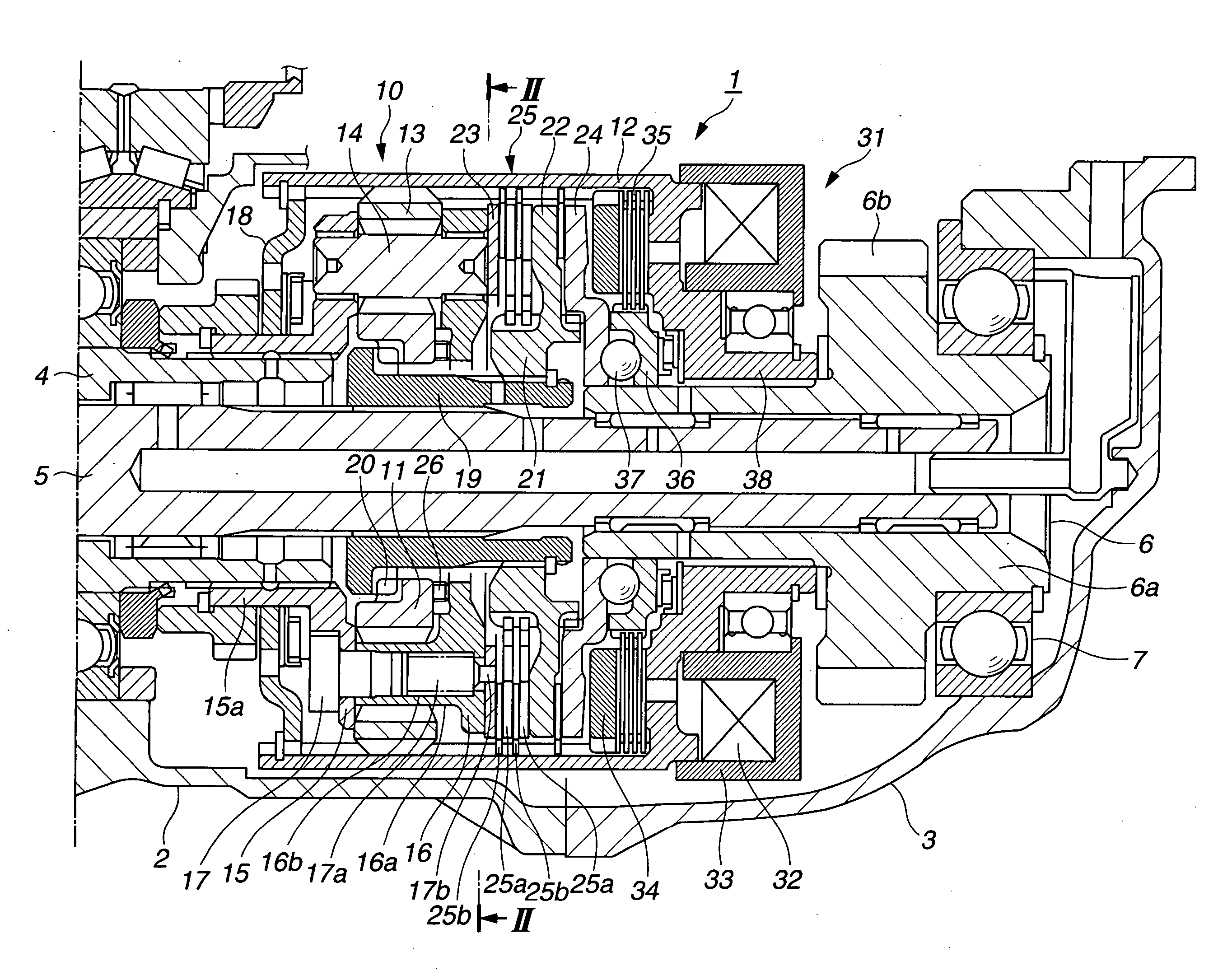
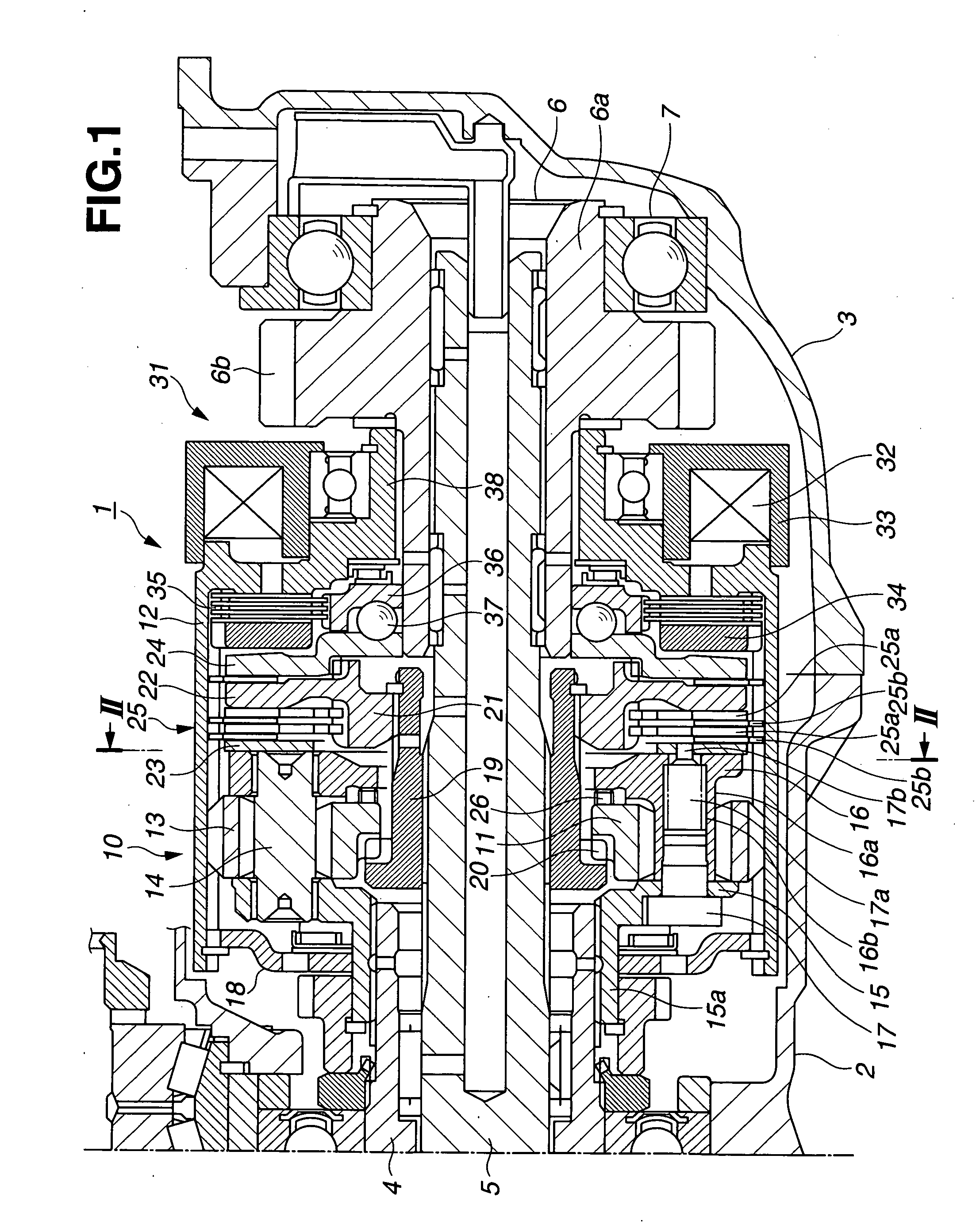
[0020] With this embodiment, a case where a differential unit with a limited slip differential mechanism is applied to a center differential will be used as an example. Accordingly, in the following description will be given with a center differential unit 1 in place of a differential unit with limited slip differential mechanism.

[0021] The center differential unit 1 is housed inside a transfer case 2 coupled to a rear part of a transmission case and an extension case 3, and an input shaft 15a of the center differential unit 1 is coupled to a rear end of a transmission output shaft 4 extending from a transmission, not shown.

[0022] Further, inside the transmission output shaft 4, a front drive shaft 5 is inserted and supported capable of relative rotation, as a first output shaft. A rear drive shaft 6, being a second output shaft, is rotatably supported via a bearing on, a rear part of the front drive shaft 5. A boss portion 6a is provided in a protruding manner on the rear part of...

second embodiment

[0060] A second embodiment is shown in FIG. 5. This embodiment is a modified example of the first embodiment, and peripheral parts that are not shown are common to the first embodiment. Also, in the drawing, structural components that are common to the first embodiment have the same reference numerals attached thereto, and their description is omitted.

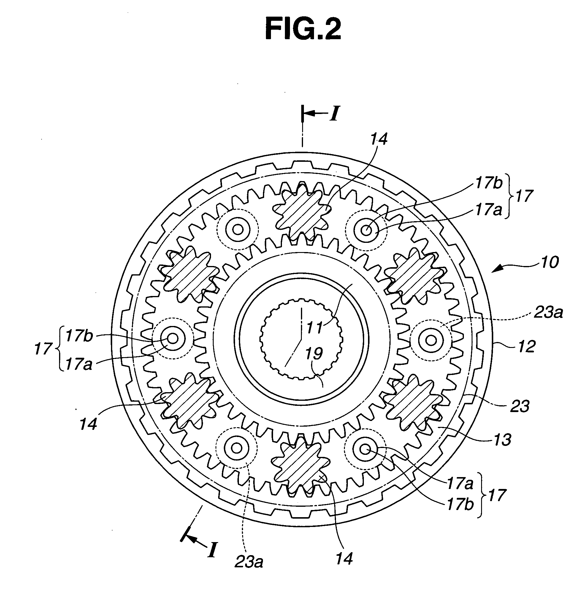
[0061] With the above described first embodiment, in order to cause the bolts 17 to function as pilot bolts, pins 17b are formed on their tip ends, and by fitting the pins 17b into check holes 23a formed in the front clutch plate 23, the front clutch plate 23 is positioned and fixed to the rear planetary carrier 16.

[0062] With this embodiment however, the bolts 17 are normal standard components, projecting portions 23b used for positioning, are formed on the front clutch plate 23 as positioning portions, and are inserted into threaded holes 16b formed as hole portions in the rear planetary carrier 16. Accordingly, with this embodimen...

third embodiment

[0064] A third embodiment is shown in FIG. 6. This embodiment is a modified example of the first embodiment, and peripheral parts that are not shown are common to the first embodiment. Also, in the drawing, structural components that are common to the first embodiment have the same reference numerals attached thereto, and their description is omitted.

[0065] With this embodiment, one end of a shaft portion 14a rotatably supported at the rear planetary carrier 16 is extended and projects slightly from the rear carrier 16, and the extending portion of the shaft portion 14a is made to function as an engagement portion. Also, instead of the check holes 23a of the first embodiment and the positioning projections 23b of the second embodiment described above, check holes 23c are formed in the front clutch plate 23 as positioning members that can be fitted around and rotatably support the shaft portions 14a.

[0066] Also, by fitting the check holes 23c formed in the front clutch plate 23 aro...


PUM


Abstract

The differential unit with a limited slip differential mechanism of the present invention comprises a planetary gear mechanism for torque distribution of drive torque inputted to an input shaft from an engine between a front drive shaft and a rear drive shaft, and a multiple disc clutch for limiting differential rotation of the planetary gear mechanism, wherein, when a clutch plate receiving clutch engaging force applied to the multiple disc clutch is fixed to a side surface of a planetary carrier of the planetary gear mechanism, pins are formed on the ends of bolts for fixing the planetary carrier, and positioning and fixing is carried out by fitting the pins into check holes formed in the clutch plate.

Description

[0001] The disclosure of Japanese Patent Application No. 2005-172975 filed on Jun. 13, 2005, including the specification, drawings and abstract, is incorporated herein by reference in its entirety. BACKGROUND OF THE INVENTION [0002] 1. Field of the Invention [0003] The present invention relates to a differential unit with a limited slip differential mechanism provided with clutch plates for receiving clutch engaging force applied to a friction clutch member at a planetary carrier side surface. [0004] 2. Description of the Related Art [0005] Conventionally, it is known to use a planetary gear mechanism as a center differential for a full-time four-wheel drive vehicle. There are also many instances in this type of center differential where a limited slip differential mechanism is provided for appropriately performing torque distribution by limiting differential action between front and rear wheels according to torque acting on the center differential. [0006] For example, Japanese pate...

Claims


Application Information

Patent Timeline
Patent Type & Authority Applications(United States)
IPC IPC(8): F16H48/06B60K23/04F16D13/52F16D13/60F16H48/10F16H48/22F16H48/295F16H48/30F16H48/34F16H48/38
CPCB60K17/20F16H48/10F16H57/082F16H48/30F16H48/22
Inventor MURAKAMI, MAMORUOWADA, NORIO
Owner SUBARU CORP
Why Eureka
Try Eureka