Bonding of target tiles to backing plate with patterned bonding agent

a technology of target tiles and bonding agents, applied in the field of sputtering targets, can solve problems such as the difficulty of forming sputtering targets of some materials

Inactive Publication Date: 2006-12-21
APPLIED MATERIALS INC
View PDF18 Cites 39 Cited by
  • Summary
  • Abstract
  • Description
  • Claims
  • Application Information

AI Technical Summary

Benefits of technology

[0010] The recesses may include a peripheral recess formed as a closed band inside the periphery of the tile areas. For rectangular tiles, the peripheral recess may include four straight and connected portions. Additional recesses may be formed inside of the peripheral recesses and preferably not connected to the peripheral recesses. Preferably also, all recesses are symmetric about the perpendicular bisectors of the target areas. The additional recesses may be one or more straight recesses. They may be intersecting straight recesses, for example, formed along the perpendicular bisectors or along the diagonals of rectangular tile areas. They may be plural straight recesses arranged in parallel. They may be formed as one or more additional closed bands.

Problems solved by technology

It is difficult to form sputtering targets of some materials, such as refractory metals, in the large sizes commensurate with the large-size panels.

Method used


Image

  • Bonding of target tiles to backing plate with patterned bonding agent
  • Bonding of target tiles to backing plate with patterned bonding agent
  • Bonding of target tiles to backing plate with patterned bonding agent

Examples


Embodiment Construction

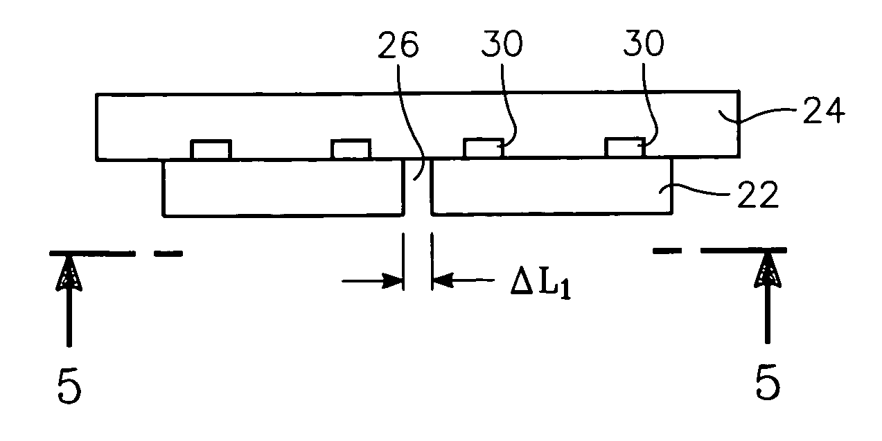
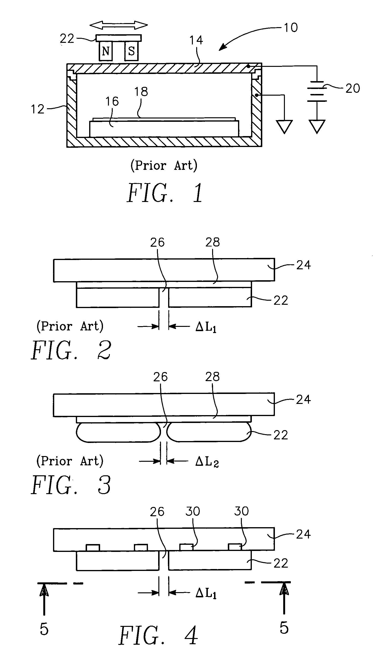
[0021] A sputtering chamber 10, schematically illustrated in the cross-sectional view of FIG. 1, includes a vacuum chamber 12, a target 14 sealed to but isolated from the electrically grounded chamber 12, and a pedestal 16 supporting a panel 18 to be sputter coated. The target 14 includes a surface layer of the material to be sputtered onto the panel 18. An argon working gas is admitted into the chamber with a pressure in the milliTorr range. A power supply 20 electrically biases the target 14 to a negative voltage of a few hundred volts, causing the argon gas to discharge into a plasma. The positive argon ions are attracted to the negatively biased target 14 and sputter target atoms from it. A magnetron 22 is scanned along the back of the target 14 to intensify the plasma and increase the sputtering rate. Some of the target atoms strike the panel 18 and form a thin film of the target atoms on its surface. The target 14 is often somewhat larger than the panel 18 being sputter coated...


PUM

PropertyMeasurementUnit
depthaaaaaaaaaa
sizeaaaaaaaaaa
sizesaaaaaaaaaa

Abstract

A target assembly including a plurality of target tiles bonded to a backing plate by adhesive, for example of indium or conductive polymer, filled into recesses in the backing plate formed beneath each of the target tiles. A sole peripheral recess formed as a rectangular close band may be formed inside the tile periphery. Additional recesses may be formed inside the peripheral recess, preferably symmetrically arranged about perpendicular bisectors of rectangular tiles. The depth and width of the recesses may be varied to control the amount of stress and the stress direction.

Description

FIELD OF THE INVENTION [0001] The invention relates generally to sputtering of materials. In particular, the invention relates to sputtering targets composed of multiple tiles. BACKGROUND ART [0002] Sputtering, alternatively called physical vapor deposition (PVD), is the most prevalent method of depositing layers of metals and related materials in the fabrication of semiconductor integrated circuits. Sputtering is now being applied to the fabrication of flat panel displays (FPDs) based upon thin film transistors (TFTs) in combination with liquid crystal devices (LCDs). Demaray et al. describe such a flat panel sputter reactor in U.S. Pat. No. 5,565,071, incorporated herein by reference in its entirety. However, other panel technologies are being pursued, such as plasma display, electron emission displays, and organic light emitting diodes (OLEDs). FPDs are typically fabricated on thin rectangular sheets of glass but other substrates are possible, such as polymeric sheets. A layer of...

Claims


Application Information

Patent Timeline
Patent Type & Authority Applications(United States)
IPC IPC(8): C23C14/00
CPCC23C14/3407H01J37/3435Y10T29/49856Y10T29/49863Y10T29/49865Y10T29/49885
Inventor LE, HIEN-MINH HUUHOSOKAWA, AKIHIRO
Owner APPLIED MATERIALS INC
Why Eureka
Try Eureka