Method for determining the position of a first moving component relatively to a second component and device for applying said method

Inactive Publication Date: 2006-12-21
DELPHI TECH INC +1
View PDF6 Cites 2 Cited by
  • Summary
  • Abstract
  • Description
  • Claims
  • Application Information

AI Technical Summary

Benefits of technology

[0057] According to a possible configuration, the photodetectors may be positioned so that each optical spot or structure obtained at the location where a diffracted ray encounters a pixel

Problems solved by technology

Devices for locating a position relatively to a fixed mark, are thus already known, based on optical technologies, w

Method used


Image

  • Method for determining the position of a first moving component relatively to a second component and device for applying said method
  • Method for determining the position of a first moving component relatively to a second component and device for applying said method
  • Method for determining the position of a first moving component relatively to a second component and device for applying said method

Examples


Example

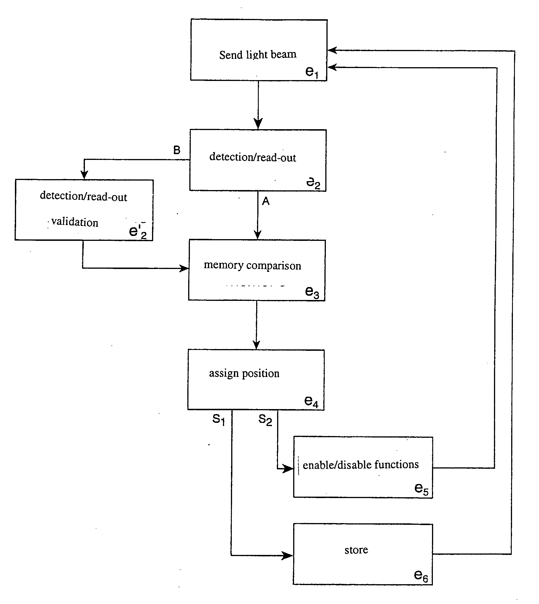
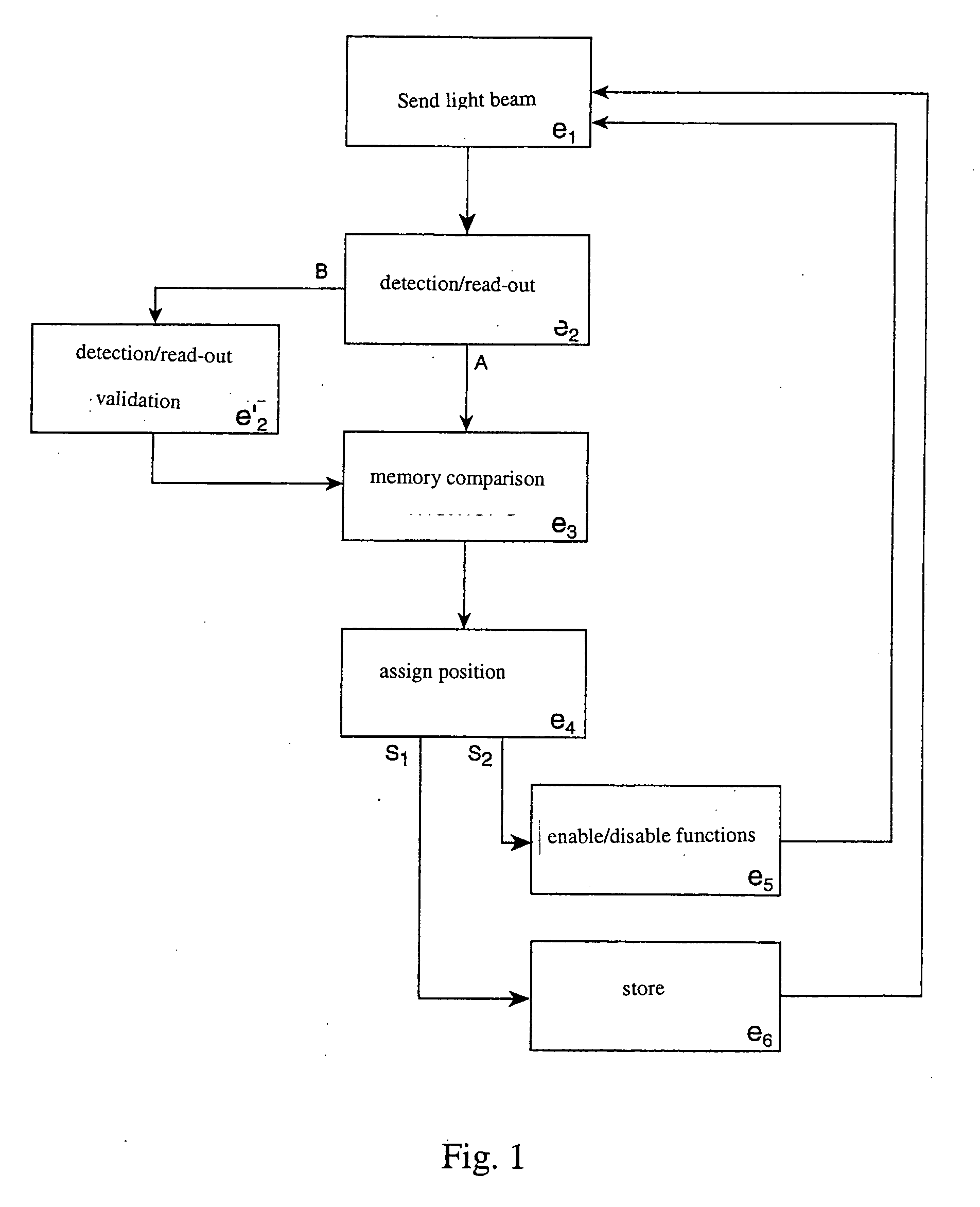
[0090] The present invention relates to a method for determining the position of one of two components in relative motion to each other. The method uses optical means. For example an exemplary functional flow chart is schematized in FIG. 1.

[0091] The method according to the invention according to step (e1) consists of directing at least one light ray emitted by a light source onto a diffractive support (1) provided for generating an optical signal. The latter is indicative of the positioning of the support relatively to a fixed mark. The optical signal is produced by the diffracted support (4) by transmission and / or by reflection.

[0092] According to a following step (e2), the method consists of detecting and reading at least one constituent optical code of the signal. This diffracted signal corresponds to a unique position of the diffractive support (1). The optical code according to step (e3) is then compared via a memory table with prerecorded data corresponding to positions. Wi...


PUM


Abstract

A method for determining the position of one of two components in relative motion with respect to each other, using optical means, comprises: directing at least one light beam emitted by a light source attached to one component towards a diffractive support attached to the second component, calculated and manufactured for generating an optical signal indicative of the positioning of said support, the optical signal being produced by the diffractive support in transmission and/or in reflection; detecting and reading at least one optical code formed by said signal, which corresponds to a unique position of the diffractive support relatively to the beam; and assigning a position to each detected optical code.

Description

TECHNICAL FIELD [0001] The present invention relates to the general technical field of systems or devices allowing a relative movement between two components to be determined and measured, for example a displacement between a mobile part and a fixed part. BACKGROUND OF THE INVENTION [0002] In an increasing number of technical applications, it has become important to be able to accurately give the position of a mobile component relatively to a fixed mark for example, occasionally at a high frequency. Such is the case for example in a vehicle steering column or in machine tools performing complex machining operations, or even, again in the automotive field, for flaps of air-conditioning systems. The possible applications are countless and explain the exponential development of positioning sensors, in particular linear or angular sensors. [0003] Several technologies may be used for detecting and measuring relative positions, the sensors which stem from the latter being, in most cases, ...

Claims


Application Information

Patent Timeline
IPC IPC(8): G06K7/10
CPCG01D5/34715
Inventor TUPINIER, LAURENTMARROUX, OLIVIER R.OCARD, LIONELMEYRUEIS, PATRICKKRESS, BERNARD
Owner DELPHI TECH INC
Why Eureka
Try Eureka