Dot position correcting apparatus, optical scanning apparatus, imaging apparatus, and color imaging apparatus

a technology of optical scanning and correction apparatus, applied in the field of color imaging apparatus, can solve the problems of image quality degradation, limited printing speed obtained by these techniques, and difficulty in setting the light intensity of semiconductor laser to a desired value, so as to achieve accurate scanning light on a scanning object without causing cost increas

Inactive Publication Date: 2006-12-21
RICOH KK
View PDF6 Cites 80 Cited by
  • Summary
  • Abstract
  • Description
  • Claims
  • Application Information

AI Technical Summary

Benefits of technology

[0020] According to an embodiment of the present invention, an optical scanning apparatus is provid

Problems solved by technology

However, the effects of increasing the printing speed obtained by these techniques are limited, and in turn, a so-called multi-beam scheme involving the use of plural light sources has been developed for responding to the demand for a further increase in the printing speed (e.g., see Japanese Laid-Open Patent Publications No. 2001-272615, No. 2003-72135, and No. 2001-350111).
Such scanning speed variations may cause image drifts that may lead to image quality degradation.
Therefore, there may be difficulties in setting the light intensity of the semiconductor laser to a desired value.
It is particularly noted that in the case of using a VCSEL (Vertical Cavity Surface Emitting Laser), temperature change and temperature crosstalk may easily occur in response to light emission and light extinction since the distance between the light sources is relatively small, and thereby, the laser may be vulnerable to light intensity fluctuation.
Also, in a case where one light source is degraded, the reduction in the light emitting level of the degraded light source

Method used


Image

  • Dot position correcting apparatus, optical scanning apparatus, imaging apparatus, and color imaging apparatus
  • Dot position correcting apparatus, optical scanning apparatus, imaging apparatus, and color imaging apparatus
  • Dot position correcting apparatus, optical scanning apparatus, imaging apparatus, and color imaging apparatus

Examples


first embodiment

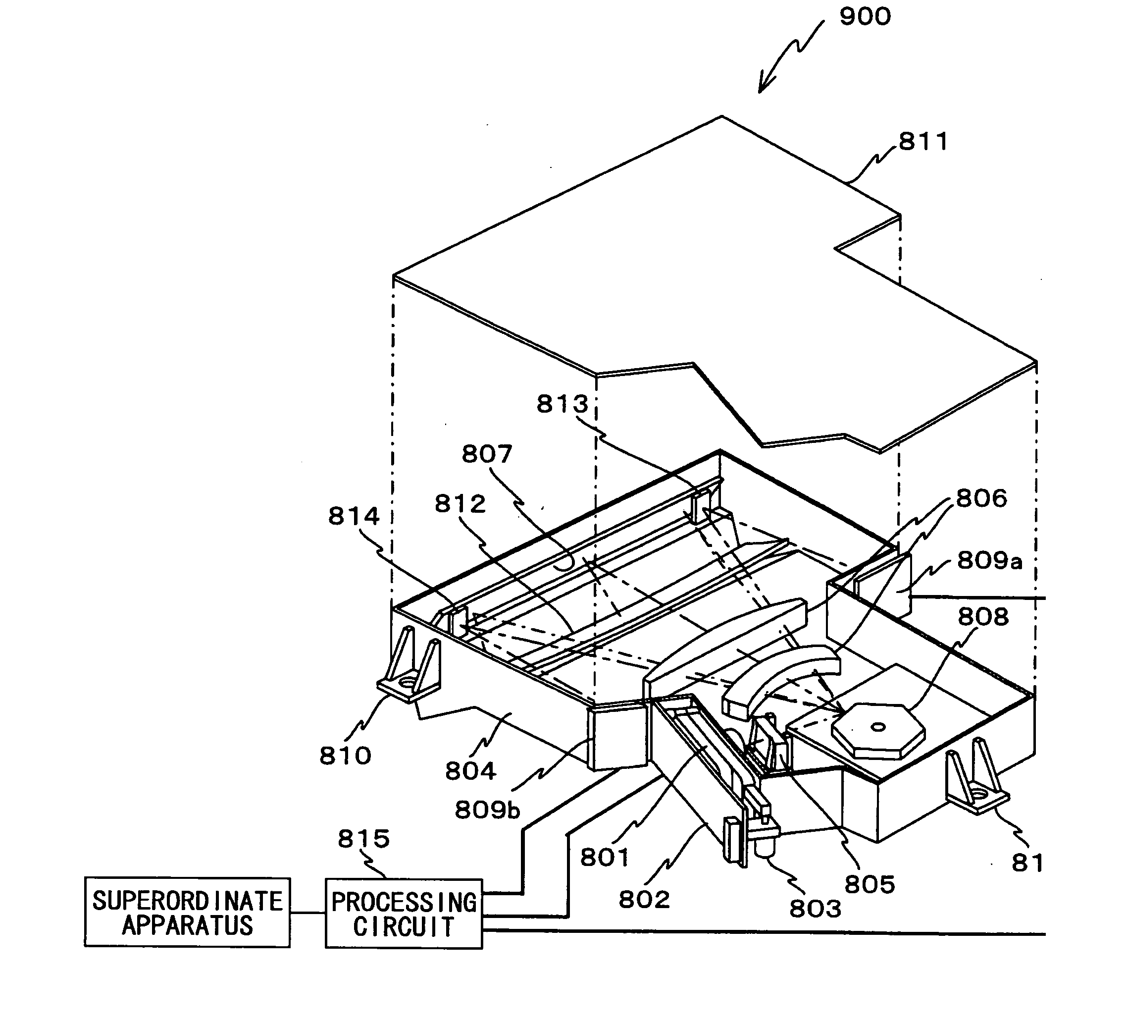
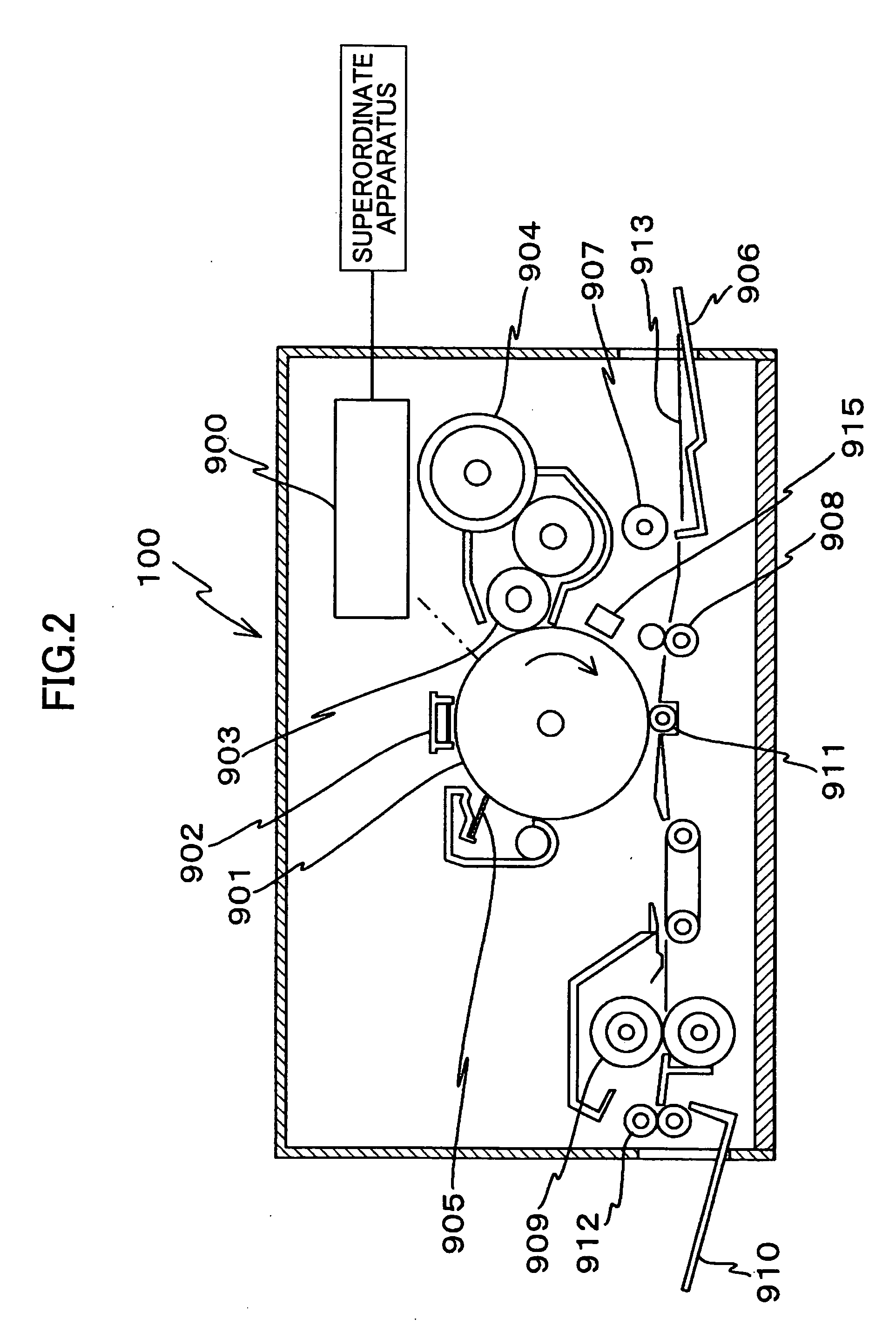
[0144] In the following, an exemplary configuration of the optical scanning apparatus 900 according to a first embodiment of the present invention is described with reference to FIGS. 2 and 3.

[0145] According to the present embodiment, the optical scanning apparatus 900 includes a light source unit 801, a collimating lens CL, a cylinder lens 805, polygon mirror 808, a polygon mirror motor (not shown) that rotates the polygon mirror 808, a fθ lens 806, a retro-reflection mirror 807, a toroidal lens 812, two reflection mirrors 813 and 814, a printed substrate 802, two PD substrates 809a and 809b, and a processing circuit 815, for example. It is noted that the collimating lens CL, the cylinder lens 805, the polygon mirror 808, the fθ lens 806, the retro-reflection mirror 807, and the toroidal lens 812 comprising an optical system that is arranged along a light path extending from the optical light unit 801 to the photoconductor drum 901 is also referred to as ‘scanning optical system’...

second embodiment

[0214] In the following, another exemplary configuration of the optical scanning apparatus 900 according to a second embodiment of the present invention is described with reference to FIGS. 20 and 21.

[0215] According to the present embodiment, the optical scanning apparatus 900 includes a light source unit 1801, a collimating lens CL, a cylinder lens 1805, polygon mirror 1808, a polygon mirror motor (not shown) that rotates the polygon mirror 808, a fθ lens 1806, a retro-reflection mirror 1807, a toroidal lens 1812, two light receiving elements 1813 and 1814, two printed substrates 1802 and 1809, and a processing circuit 1815, for example. It is noted that the collimating lens CL, the cylinder lens 1805, the polygon mirror 1808, the fθ lens 1806, the retro-reflection mirror 1807, and the toroidal lens 1812 comprising an optical system that is arranged along a light path extending from the optical light unit 1801 to the photoconductor drum 901 is also referred to as ‘scanning optica...

third embodiment

[0276] In the following, a third embodiment of the present invention is described.

[0277]FIG. 39 is a block diagram showing a configuration of a pixel clock generating unit 210 used in the third embodiment of the present invention. The pixel clock generating unit 210 of FIG. 39 includes a high frequency clock generating circuit 211 as a high frequency clock generating unit for generating a high frequency clock, a transition detecting circuit 212 as a first detecting unit for detecting signal transition of a first clock (clock 1), a control signal generating circuit 213 as a first control signal generating unit for generating a first control signal (control signal 1a and 1b) based on an output from the first detecting unit and first control data (control data 1), a clock 1 generating circuit 214 as a first signal transitioning unit for inducing transition of a signal at a first change-point timing of the high frequency clock based on the first control signal and outputting the signal...


PUM


Abstract

An optical scanning apparatus is disclosed that includes a light source unit having plural main light sources that are two-dimensionally arranged in the main scanning direction and the sub scanning direction, and plural sub light sources that are arranged between rows of the main light sources aligned in the main scanning direction. The optical scanning apparatus also includes an optical system configured to scan light emitted from the light source unit on a scanning object to form an image on the scanning object, and a control apparatus configured to adjust a main scanning direction image position by controlling two of the main light sources that are juxtaposed to each other with respect to the main scanning direction and adjust a sub scanning direction image position by controlling a main light source and a sub light source that are adjacent to each other.

Description

BACKGROUND OF THE INVENTION [0001] 1. Field of the Invention [0002] The present invention relates to an optical scanning apparatus that is configured to scan light emitted from a light source on a scanning object, and an imaging apparatus that includes such an optical scanning apparatus. The present invention also relates to a dot position correcting apparatus, an optical scanning apparatus, and an imaging apparatus such as a laser printer or a digital copying machine and a color imaging apparatus that use such dot position correcting apparatus and optical scanning apparatus. [0003] 2. Description of the Related Art [0004] An imaging apparatus such as a laser printer or a digital copier may be configured to focus light emitted from a light source that is modulated according to image information on a photoconductor (scanning object) via a polygon mirror and a scanning optical system such as a scanning lens, and scan the light on the surface of the photoconductor in a predetermined di...

Claims


Application Information

Patent Timeline
IPC IPC(8): G02B26/08
CPCB41J2/0057G02B26/125G02B26/127H04N1/047H04N1/1135H04N2201/04791H04N1/195H04N2201/0082H04N2201/04729H04N2201/04731H04N2201/04789H04N1/12H04N2201/0471H04N2201/04734H04N2201/04744H04N2201/03158H04N2201/04767
Inventor ISHIDA, MASAAKINIHEI, YASUHIROOMORI, ATSUFUMIOZASA, DAN
Owner RICOH KK
Why Eureka
Try Eureka