Projecting device with energy recycling function

a projector and energy recycling technology, applied in the field of projectors, can solve the problems of reducing the power utilization efficiency of the projector, wasting too much heat or light, and generating lots of heat in the light source, and achieve the effect of reducing energy was

Inactive Publication Date: 2006-12-21
BENQ CORP
View PDF0 Cites 29 Cited by
  • Summary
  • Abstract
  • Description
  • Claims
  • Application Information

AI Technical Summary

Benefits of technology

[0008] It is therefore an object of the invention to provide a projecting device with energy recycling function to reduce energy waste by recycling redundant heat or light.

Problems solved by technology

However, the light source generates lots of heat in the light emitting process.
If the temperature inside the projector gets too high, electronic components in the projector will be damaged, thereby generating an error operation.
However, for the heat is a kind of energy like the light, too much heat or light wasted will reduce power utilizing efficiency of the projector.

Method used


Image

  • Projecting device with energy recycling function
  • Projecting device with energy recycling function
  • Projecting device with energy recycling function

Examples


embodiment one

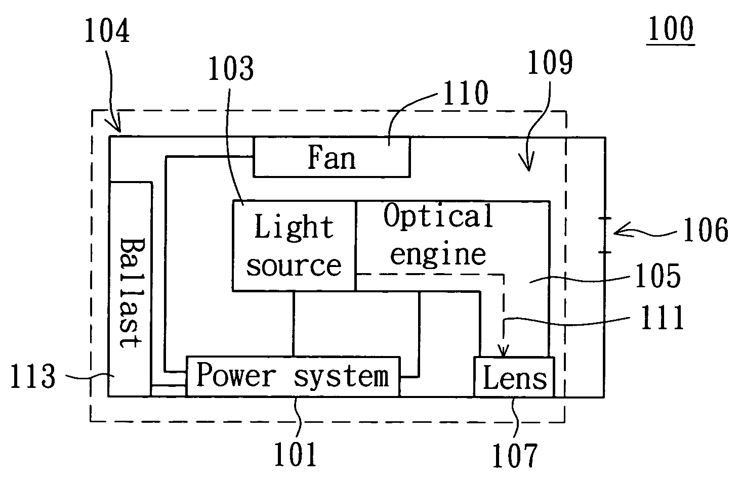
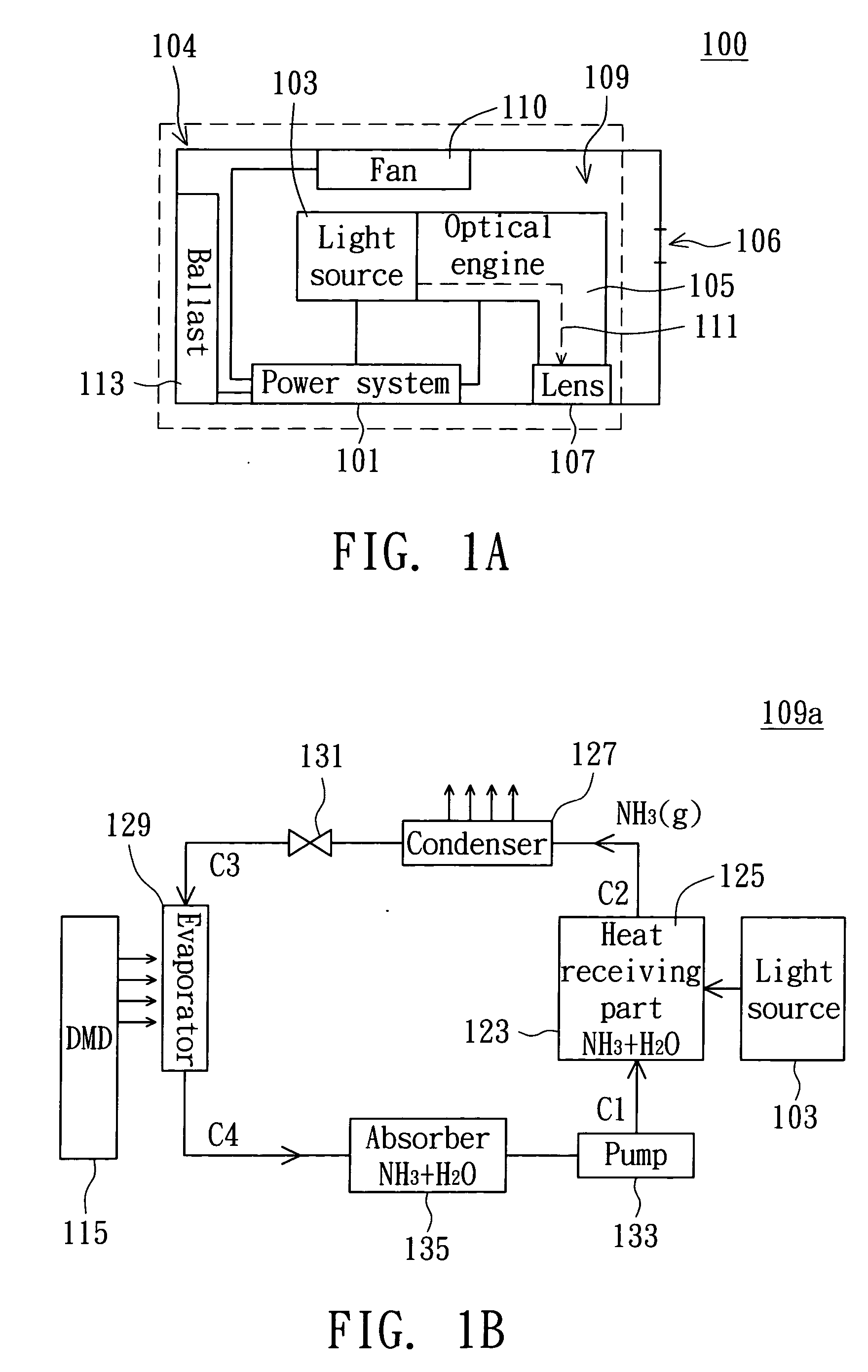
[0019] Referring to FIG. 1A, a block diagram of a projecting device according to the first embodiment is shown. The projecting device 100 mainly comprises a power system 101, a light source 103, an optical engine 105, a lens 107, and an energy recycling module (in the dotted part of FIG. 1A) 109. The power system 101 supplies powers to main components, such as the light source 103 and the optical engine 105, and supplies electric power to a fan 110 and a ballast 113. The ballast 113 is for stabilizing rectification and lighting up the light source 103. The light emitted by the light source 103 is guided by the optical engine 105 to from a projecting image via the lens 107. The light path 111 is formed as the light goes from the light source 103 to the lens 107 via the optical engine 105. The casing 104 of the projecting device 100 covers the light source 103, the optical engine 105, and the lens 107. Moreover, an opening 106 is formed on the casing 104 of the projecting device 100. ...

embodiment two

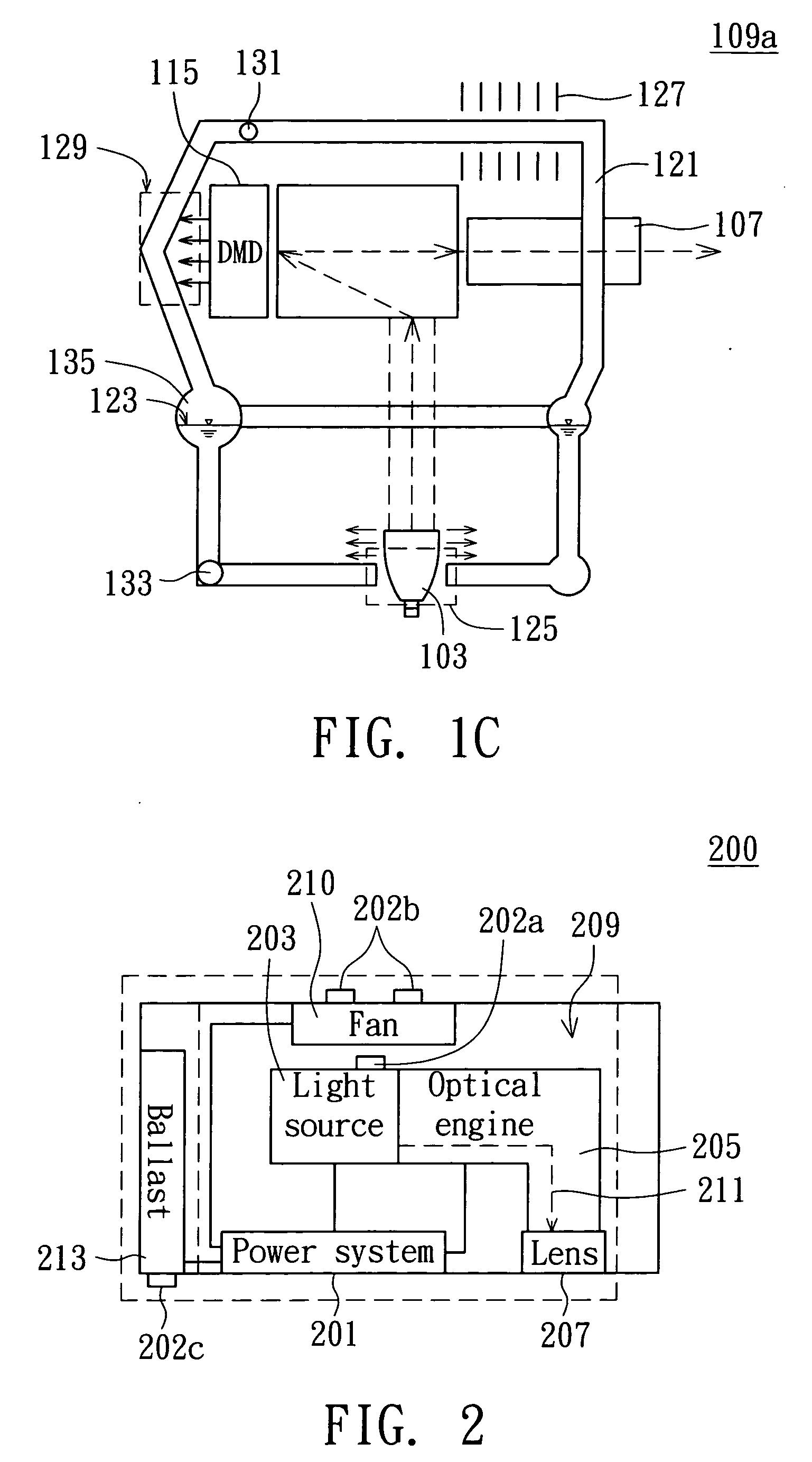
[0023] Referring to FIG. 2, a configuration diagram of a thermoelectric semiconductor according to the second embodiment of the invention is shown. Different from the first embodiment, thermoelectric semiconductors 202a-202c are further added to the flow-path system 109a for absorbing heat and transforming the heat into electric energy. In the projecting device 200, the region having higher temperature difference can be found out according to the temperature distribution. For example, the temperature nearby the light source 203 is usually higher than the temperature relatively away from the light source 203, and the temperature difference in that region would be higher. Therefore, the heat propagating effect at this region will be better and the thermoelectric semiconductor 202a disposed therein can have a higher energy recycling efficiency. For example, the thermoelectric semiconductor 202a may be disposed at one side of the light source 203. The thermoelectric semiconductor 202b i...

embodiment three

[0024] Different from the flow-path system 109a, the heat recycling method of the embodiment is performed by using a Stirling engine. Referring to FIG. 3A and FIG. 3B, FIG. 3A is a relation diagram between the pressure and specific volume of the Stirling engine according to the third embodiment of the invention. FIG. 3B is a schematic diagram of a piston motion in the Stirling engine according to the third embodiment of the invention. Similar to the first embodiment, the Stirling engine 320 is disposed in the neighborhood of the light source, such as at one side of the light source. The Stirling engine 320 may be disposed at one side of the optical engine as well due to the same reason. Gas in the Stirling engine 320 is heated to push the piston 322 to move back and forth in the direction X1 by the high-temperature light source or other electronic components, wherein P is the pressure, V is the specific volume and P×V is the work. By continuously changing the specific volume V and / o...


PUM


Abstract

A projecting device with energy recycling function comprises a power system, a light source, an optical engine, a lens and an energy recycling module. The light source which receives power from the power system is for generating a beam of light. The optical engine which receives power from the power system is for guiding the light generated by the light source. The lens is for receiving the light guided by the optical engine to generate a projecting image, and the light forms a light path from the light source to the lens via the optical engine. The energy recycling module is for recycling at least one of heat energy and light energy generated by at least one of the light source and the optical. engine.

Description

[0001] This application claims the benefit of Taiwan application Serial No. 94119907, filed Jun. 15, 2005, the subject matter of which is incorporated herein by reference. BACKGROUND OF THE INVENTION [0002] 1. Field of the Invention [0003] The invention relates in general to a projecting device, and more particularly to a projecting device with energy recycling function. [0004] 2. Description of the Related Art [0005] Projecting devices, such as projectors, are widely applied in offices, conferences, laboratories, schools and even family theaters. [0006] A common projector mainly comprises a power system, a light source, an optical engine and a lens. The power system mainly supplies power to the light source and components in the optical engine. The light emitted from the light source is transmitted through the optical engine and projected out to form a projecting image via the lens. However, the light source generates lots of heat in the light emitting process. If the temperature i...

Claims


Application Information

Patent Timeline
Patent Type & Authority Applications(United States)
IPC IPC(8): F21V29/00
CPCF21S9/037F21V29/00F21V29/30H04N9/3144H04N5/7458H04N9/3141H04N5/74F21V29/56Y02W30/82
Inventor WANG, BANG-JILI, CHANG-CHIEN
Owner BENQ CORP
Why Eureka
Try Eureka