Optical fiber lateral scanner for a miniature optical fiber probe

a miniature optical fiber and optical fiber technology, applied in the field of optical imaging, can solve the problems of difficult placement of coils around magnets inside the probe body, inability to incorporate performance data, and high manufacturing complexity, and achieve the effect of convenient assembly

Inactive Publication Date: 2006-12-21
IMALUX CORP
View PDF8 Cites 9 Cited by
  • Summary
  • Abstract
  • Description
  • Claims
  • Application Information

AI Technical Summary

Benefits of technology

[0008] Accordingly, there is a need for an optical fiber lateral scanner to be used in a miniature optical fiber probe that is less critical to the to the shape and dimensional tolerances of scanner elements and easier to assemble. It is another object of the present invention to provide a potential for further miniaturization of the optical fiber lateral scanner and probe keeping a given scanning range. SUMMARY OF THE INVENTION
[0019] In the present invention the new designs of the electromagnetic system are less critical to the shape and dimensional tolerances of the assembly and its elements. These designs provide a potential for a less difficult assembly process and for further miniaturization. A miniature optical fiber probe, which incorporates the optical fiber lateral scanner of the invention, will inherit all its benefits.

Problems solved by technology

A disadvantage of above described optical fiber lateral scanners is that they do not allow for performance data necessary to be incorporated in a miniature optical fiber probe used in an OCT apparatus, in particular, miniature size, combined with required deflection of the optical fiber.
However, limitation common to both the optical fiber lateral scanner and the miniature optical fiber probe referred to in U.S. Pat. No. 6,608,684 regards the complexity for manufacturing due to the fact that the design is very critical to the shape and dimensional tolerances of scanner elements and assembly.
In particular, placing the coil around the magnet inside the probe body is very difficult and some critical bonding places are extremely hard to access.

Method used


Image

  • Optical fiber lateral scanner for a miniature optical fiber probe
  • Optical fiber lateral scanner for a miniature optical fiber probe
  • Optical fiber lateral scanner for a miniature optical fiber probe

Examples


Embodiment Construction

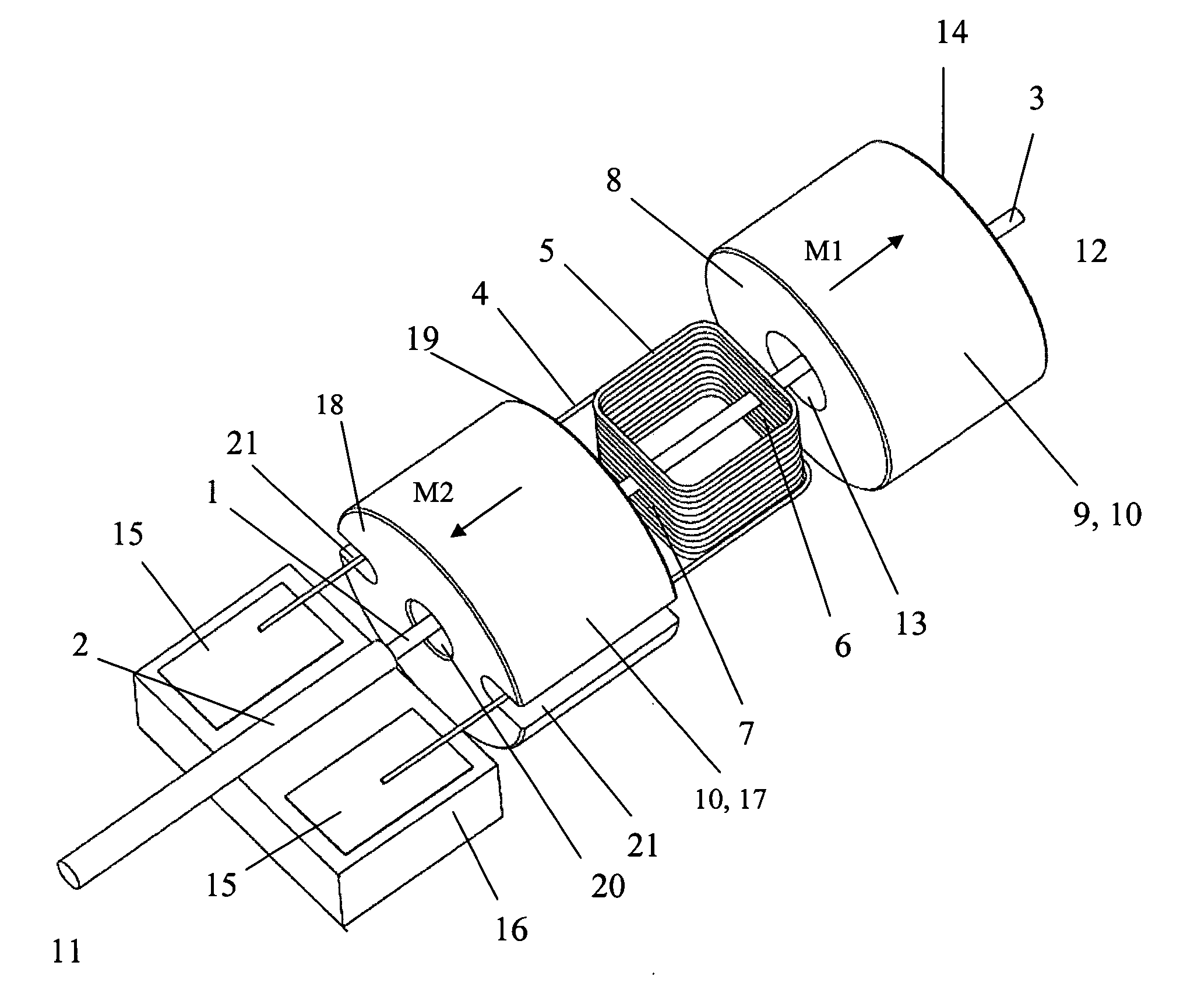
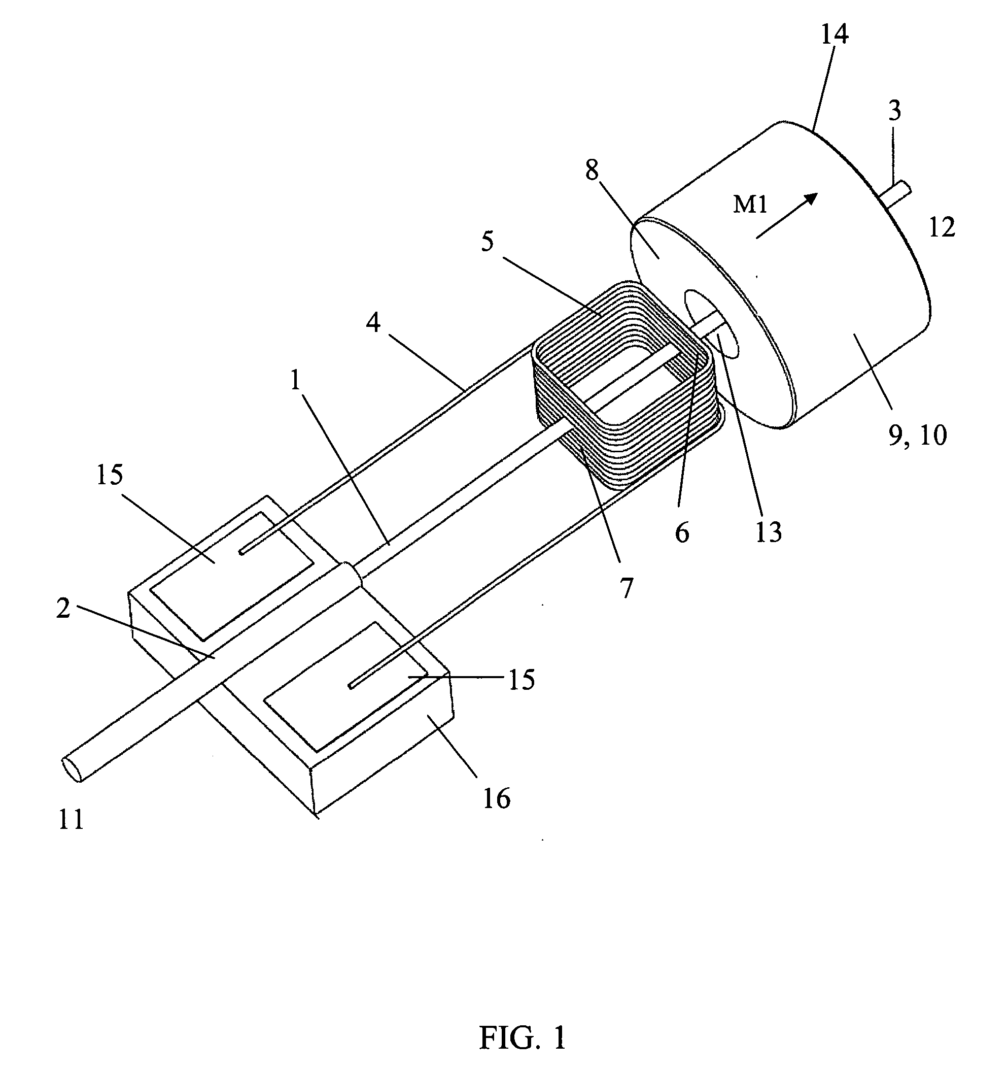
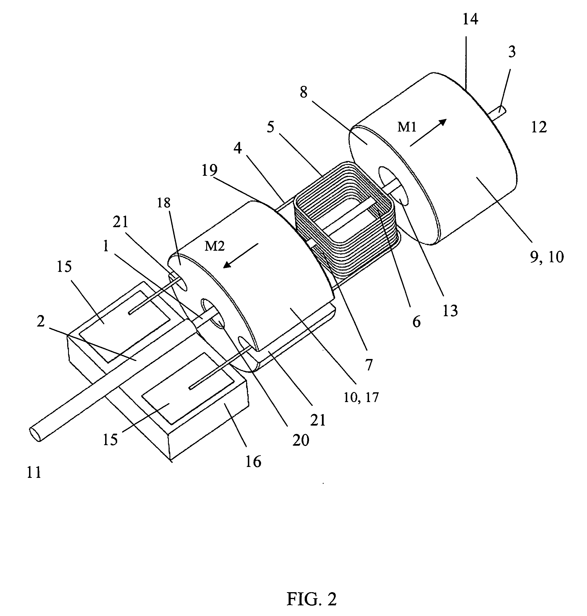
[0030] Referring to operation of the optical fiber lateral scanner illustrated in FIG. 1, an optical radiation from a source of optical radiation, which is not shown in the drawing, passes along an optical fiber 1 from its proximal part 2 to its distal part 3. The optical fiber 1 is single-mode and is an element of a movable part of the optical fiber lateral scanner. Another element of the movable part is a current conductor 4, which is rigidly fixed to the optical fiber 1 and can be made from insulated copper wire. The current conductor 4 includes at least one loop 5. The plane of the current conductor loop 5 is substantially aligned with the own axis (not shown in the drawing) of the optical fiber 1. The current conductor loop 5 includes a first part 6 and a second part 7. In the embodiment of FIG. 1 the first part 6 of the current conductor loop 5 is adjacent to a proximal end face 8 of a first permanent magnet 9 of a permanent magnet system 10. The second part 7 of the current c...


PUM


Abstract

The present invention relates to an optical fiber magnetic scanning arrangement for a miniature optical fiber probe and can be applied for optical beam delivery in various optical imaging techniques. The arrangement is of the type where an optical fiber is rigidly fixed to a current conductor and serving as a flexible cantilever with a capability for the distal part of the optical fiber of being deflected in a direction substantially orthogonal to its own axis. New designs of the magnetic system are less critical to the shape and dimensional tolerances of scanner elements and assembly. These designs provide a potential for a less difficult assembly process and for further miniaturization. According to one aspect of the invention the permanent magnet system includes at least a first permanent magnet with a magnetization direction that is substantially aligned with the own axis of the optical fiber. The current conductor loop is placed adjacent to the one of the end faces of the first permanent magnet. According to another aspect of the invention the permanent magnet system includes at least a first permanent magnet piece with a magnetization direction that is substantially orthogonal to the own axis of the optical fiber. The permanent magnet piece extends in a direction substantially aligned with the own axis of the optical fiber and has an inner surface, the current conductor loop being adjacent to at least a part of the inner surface of the first permanent magnet piece. According to another aspect of the invention the permanent magnet system includes a permanent magnet of a hollow cylinder type with a substantially radial magnetization direction. The permanent magnet cylinder extends in a direction substantially aligned with the own axis of the optical fiber. The current conductor loop is placed inside the permanent magnet cylinder. A miniature optical fiber probe, which incorporates the optical fiber lateral scanner of the invention, will inherit all its benefits.

Description

TECHNICAL FIELD [0001] The present invention relates to the field of optical imaging and more specifically to an optical fiber magnetic scanning arrangement for a miniature optical fiber probe and can be applied for optical beam delivery in various optical imaging techniques, such as optical coherence tomography (OCT). BACKGROUND ART [0002] Prior art optical fiber lateral scanners of the type are known to comprise a stationary part, including a bearing support and an electromagnet, and a moving part including a permanent magnet attached to an optical fiber (see, e.g., U.S. Pat. No. 3,470,320; U.S. Pat. No. 5,317,148). In these devices, the optical fiber is anchored at one end to a bearing support and serves as a flexible cantilever, whereas the free end of the optical fiber is arranged such, that it can move in the direction perpendicular to its own axis. The permanent magnet is placed in a gap between the poles of the electromagnet. [0003] A prior art optical fiber lateral scanner ...

Claims


Application Information

Patent Timeline
Patent Type & Authority Applications(United States)
IPC IPC(8): G02B6/26
CPCG02B6/32G02B26/10G02B6/3572G02B6/3502
Inventor PIYEVSKY, SERGEY M.FELDCHTEIN, FELIX I.GELIKONOV, GRIGORY V.
Owner IMALUX CORP
Why Eureka
Try Eureka