Pocket ventilator

a pocket ventilator and ventilator technology, applied in the field of papermaking, can solve the problems of increasing the travel speed of the web in the pocket, directly and uncontrollably affecting the quality and quantity of air being processed in the pocket, and complex operation involving massive and expensive machines

Inactive Publication Date: 2006-12-28
ENERQUIN AIR
View PDF8 Cites 4 Cited by
  • Summary
  • Abstract
  • Description
  • Claims
  • Application Information

AI Technical Summary

Benefits of technology

[0009] It is therefore an aim of the present invention to provide an apparatus for drying a paper web in a papermaking machine wherein an airflow within drying pockets thereof is controlled.
[0011] More specifically, in accordance with the present invention, there is provided an apparatus for drying a paper web in a papermaking machine, the apparatus comprising at least three substantially axially parallel rotatable drying cylinders, a first cylinder and a third cylinder being vertically offset from a second cylinder, the web being consecutively trained over the first, second and third cylinders defining a pocket therebetween, the apparatus further comprising an elongated structure longitudinally disposed adjacent and substantially parallel to the first cylinder and between the first and third cylinders, a first lateral edge of the structure proximal to a peripheral surface of the first cylinder defining a gap therewith such that the web trained thereon may travel toward the second cylinder while the structure reduces a flow of air dragged into the pocket by a motion of the web from the first cylinder to the second cylinder.
[0015] C) reducing an inflow of air dragged into the pocket by a motion of the web from the first cylinder to the second cylinder using the structure as an air block to the pocket.
[0016] Still in accordance with the present invention, there is provided a device for controlling an injection of air in a drying pocket of a paper web drying apparatus, the web drying apparatus comprising at least three substantially axially parallel rotatable drying cylinders, a first cylinder and a third cylinder being vertically offset from a second cylinder and the web being consecutively trained thereover defining the pocket therebetween, the device comprising an elongated structure longitudinally mounted adjacent and substantially parallel to the first cylinder and between the first and third cylinders, a first lateral edge of the structure proximal to a peripheral surface of the first cylinder defining a gap therewith such that the web trained thereon may travel toward the second cylinder while the structure reduces an inflow of air dragged into the pocket by a motion of the web from the first cylinder to the second cylinder.
[0017] Still further in accordance with the present invention, there is provided an apparatus for drying a paper web, the apparatus comprising an upper row of rotatable drying cylinders, a lower row of rotatable drying cylinders, the web being trained through the rows forming at least one pocket, a porous dryer felt urging the web against the drying cylinders of the upper row while the web is trained thereover, a felt roller mounted between two successive drying cylinders of the upper row, referred as first upper and second upper drying cylinders, the felt roller guiding the felt away from the first upper cylinder and toward the second upper cylinder, a pocket ventilation system comprising means for establishing a positive pressure zone of air between the first upper cylinder and the felt roller outside the pocket causing air to penetrate in the pocket through the felt and means for producing an air jet between a cleft defined between the felt roller and the felt and a cleft defined between the second upper cylinder and the felt outside the pocket and directed away therefrom causing a negative pressure zone and constituting means for extracting moisture laden air from the pocket through the felt and, an elongated structure longitudinally mounted to the ventilation system adjacent and substantially parallel to the first upper cylinder, a first lateral edge of the structure proximal to a peripheral surface of the first upper cylinder defining a gap therewith such that the web trained thereon may travel through the gap while the structure reduces an inflow of air dragged into the pocket by a motion of the web from the first upper cylinder to the second row.

Problems solved by technology

Papermaking is a sophisticated operation involving massive and very expensive machines.
Of particular interest here are problems generated during the web drying process resulting from the increased travel speed of the web therein.
Namely, as the web travels between the drying cylinders at high speed, a current of hot and moist air is dragged along with the surface of the web and penetrates the pockets, thereby directly and uncontrollably affecting the quality and quantity or air being processed in the pocket.
This in turn reduces the controllability and efficiency of the drying process.

Method used


Image

  • Pocket ventilator
  • Pocket ventilator
  • Pocket ventilator

Examples


Embodiment Construction

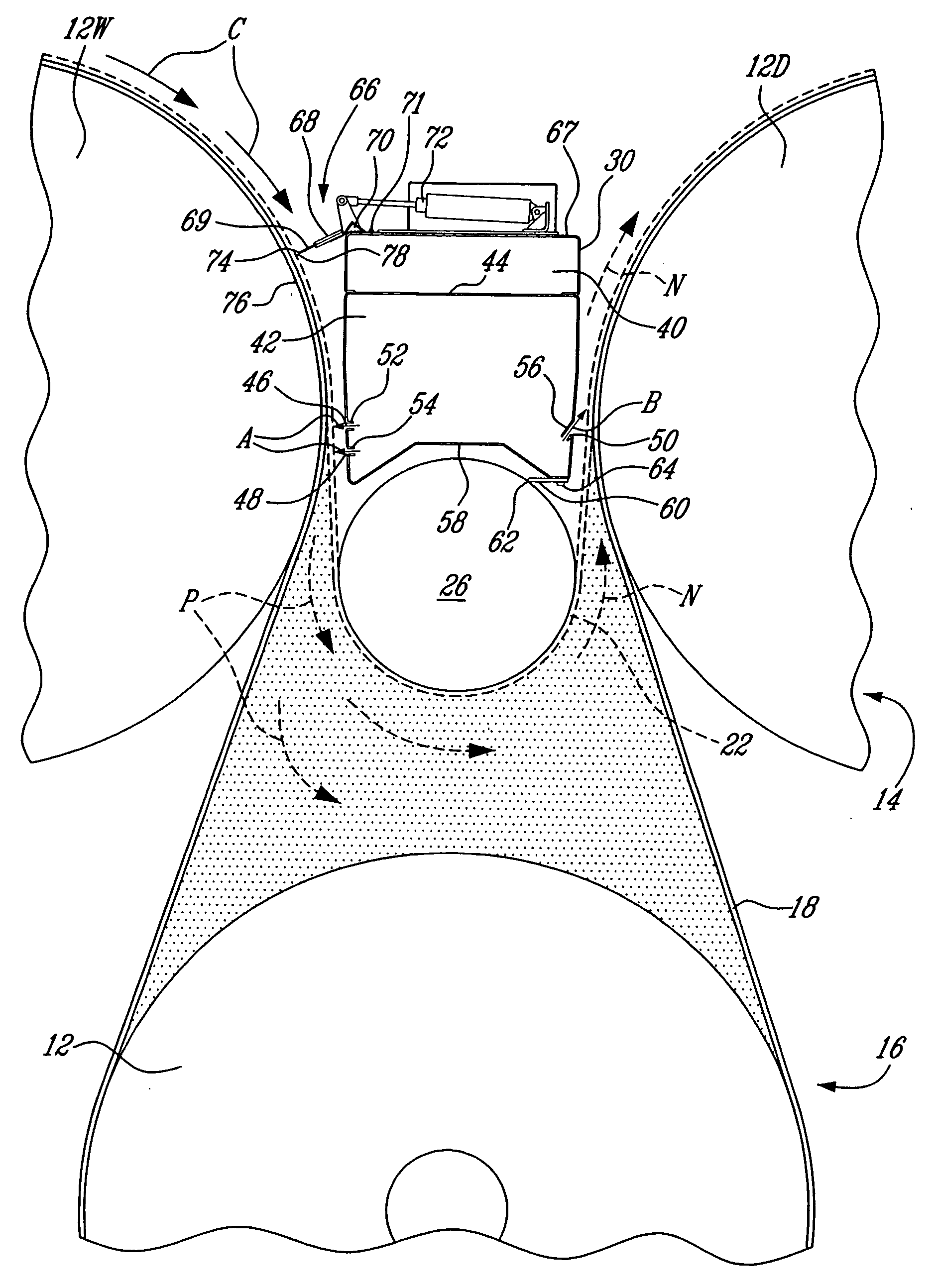
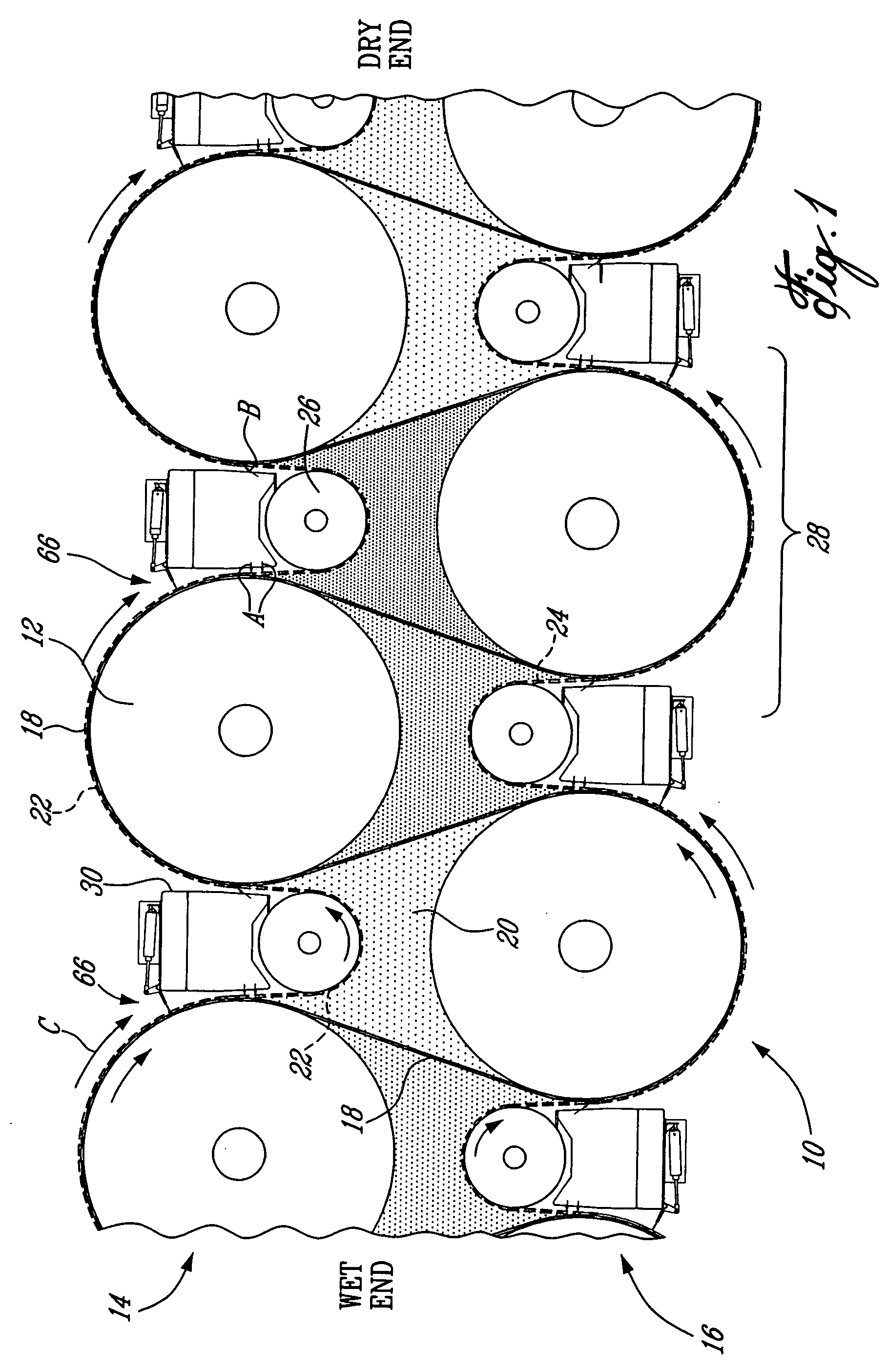
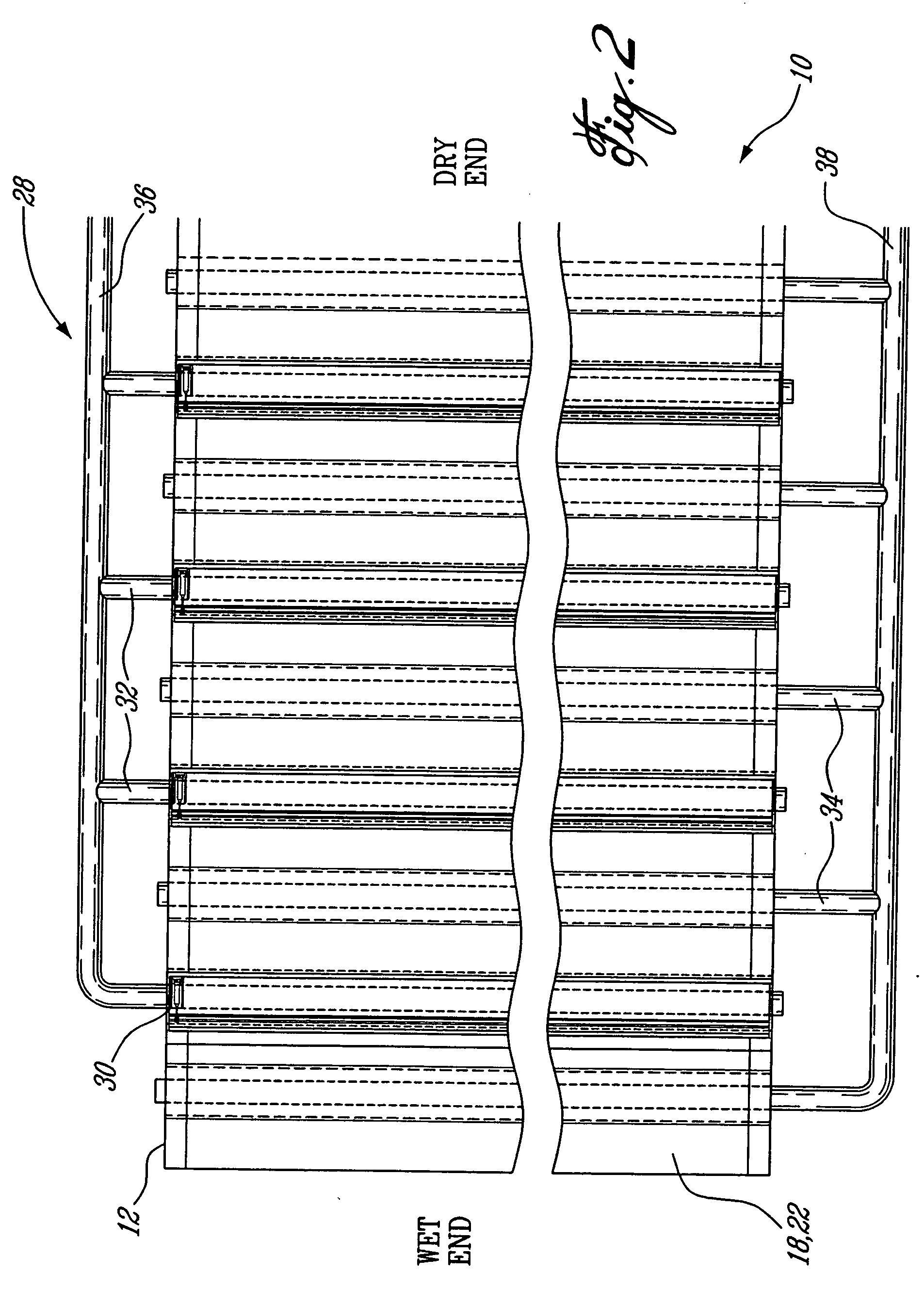
[0024] Referring to FIGS. 1 and 2, and in accordance with an illustrative embodiment of the present invention, a web dryer, generally referred to using the numeral 10, will now be described. The web dryer 10 comprises a plurality of heated drying cylinders 12 arranged in two vertically spaced apart rows, namely an upper row 14 and a lower row 16. A web 18 to be dried is trained over the cylinders 12 in a serpentine path defining a series of pockets 20, the pockets 20 being marked in FIG. 1 by stippled areas.

[0025] Two dryer felts 22 and 24, illustrated in dotted lines for illustrative purposes so as to be distinguishable from the full lines used to illustrate the paper web 18 and associated with the cylinder rows 14 and 16 respectively, are provided to press the web 18 against the cylinders 12 for a better heat transfer therebetween and consequently to increase the efficiency of the dryer 10. The upper dryer felt 18 is in wrapping engagement with each cylinder 12 of the upper row 1...


PUM


Abstract

A paper web drying apparatus is described as comprising a device for controlling an injection of air in a drying pocket of the drying apparatus. The web drying apparatus generally comprises at least three substantially axially parallel rotatable drying cylinders, first and third cylinders being vertically offset from a second cylinder and the web being consecutively trained thereover defining the pocket therebetween. The apparatus may define a traditional pocket, an offset pocket, or other such pocket configurations known in the art. The device comprises an elongated structure longitudinally mounted adjacent and substantially parallel to the first cylinder and between the first and the third cylinders. A first lateral edge of the structure may be positioned proximal to a peripheral surface of the first cylinder thereby defining a gap therewith such that the web trained thereon may travel toward the second cylinder unobstructed by the structure while the structure reduces an inflow of air dragged into the pocket by a motion of the web from the first to the second cylinder.

Description

FIELD OF THE INVENTION [0001] The invention relates to the art of papermaking and, more particularly, to a ventilation system for use in a dryer section of a paper machine. BACKGROUND OF THE INVENTION [0002] Papermaking is a sophisticated operation involving massive and very expensive machines. The papermaking process requires that water be removed from the initial pulp fiber solution as the paper is formed. The pulp fiber solution, once in the drying section of a papermaking machine, is referred to as the paper web. The paper web is supported as it travels across the machine following a path during which moisture is progressively removed therefrom. The support is provided by endless sheets of porous fabric, felts, wires or other water and gas permeable support means, all of which are generically referred to as the “felt” or “felts” in the description and appended claims. [0003] The paper web travels from what is referred to as the wet end of the machine to the dry end thereof. In i...

Claims


Application Information

Patent Timeline
Patent Type & Authority Applications(United States)
IPC IPC(8): F26B11/02B65G1/00H01L21/00
CPCD21F5/046H01L21/67161H01L21/67184H01L21/67173H01L21/67178H01L21/67167
Inventor THIFAULT, DOMINIQUE
Owner ENERQUIN AIR
Why Eureka
Try Eureka