Electrical junction box for a solar cell module

a solar cell module and electric junction technology, applied in the direction of electrically conductive connections, photovoltaics, coupling device connections, etc., can solve the problems of reducing output, affecting the overall operation of the solar cell module, and the entire module cannot deliver current. , to achieve the effect of simple and reliable connection of thin conductor strips

Inactive Publication Date: 2006-12-28
GUNTHER SPELSBERG GMBH CO
View PDF9 Cites 50 Cited by
  • Summary
  • Abstract
  • Description
  • Claims
  • Application Information

AI Technical Summary

Benefits of technology

[0013] Therefore, a primary object of the present invention is to devise a junction box for a solar cell module with which simple and reliable connection of thin conductor strips routed out of a solar cell module is enabled.
[0014] Proceeding from the initially described 
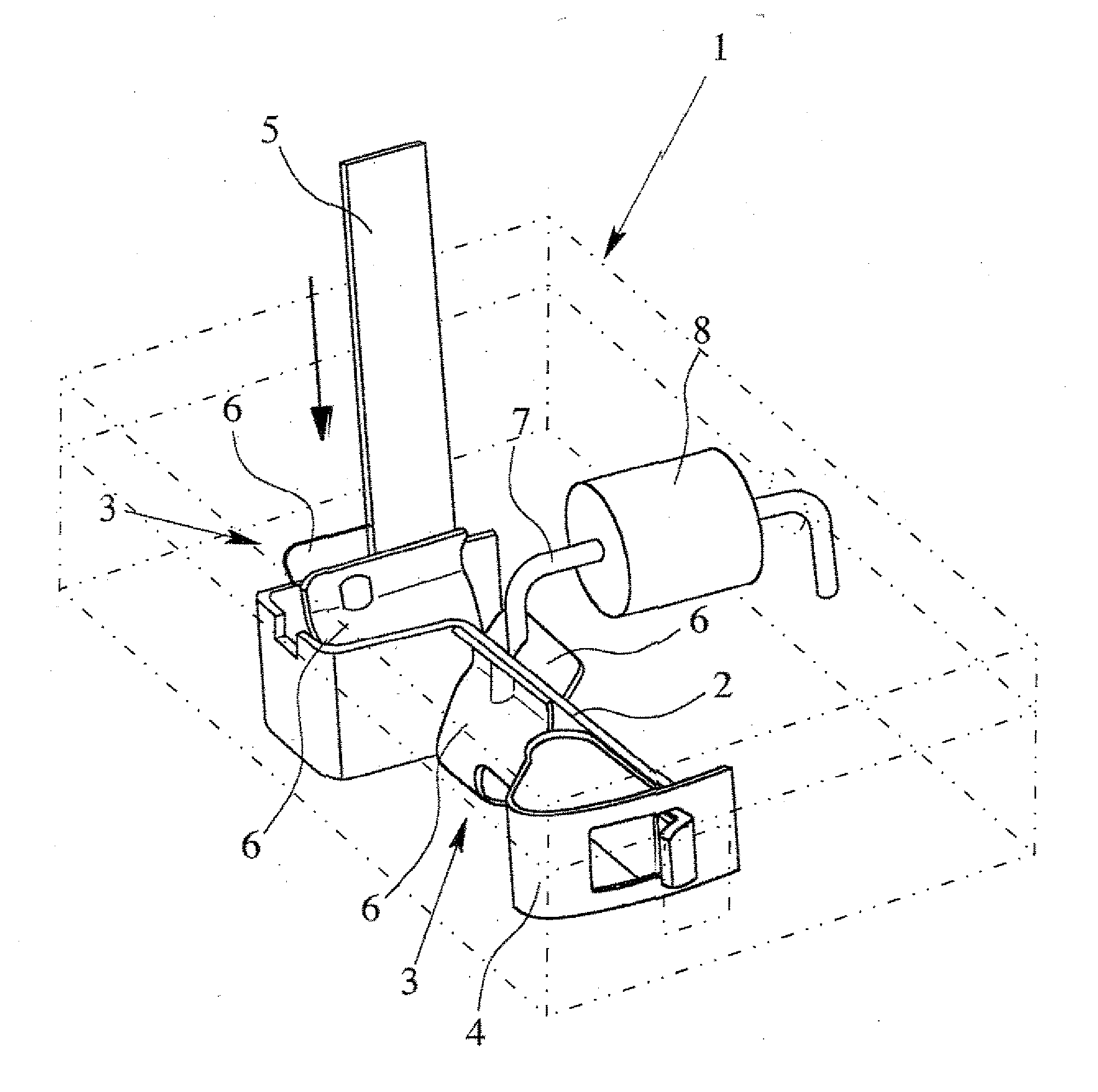
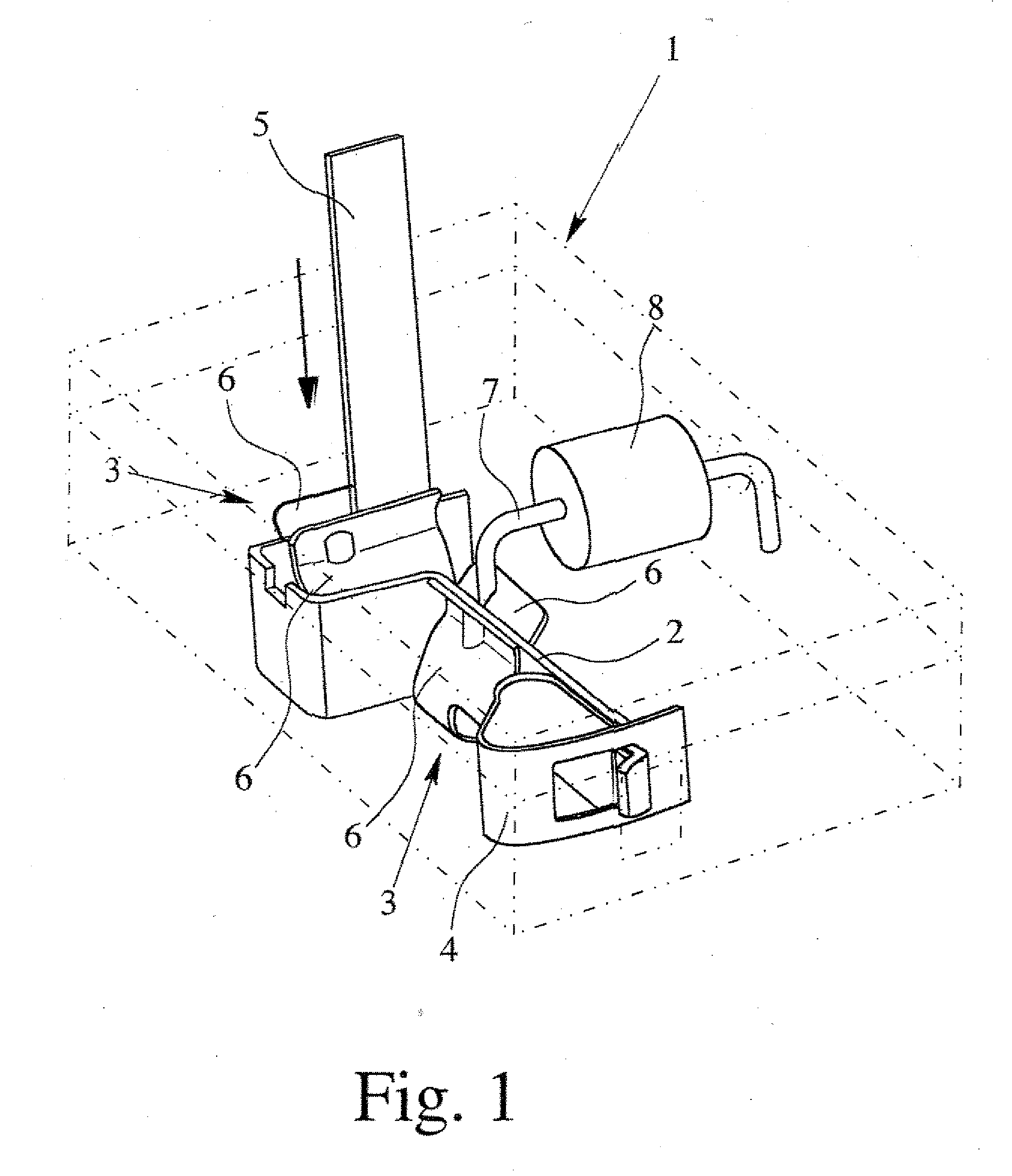
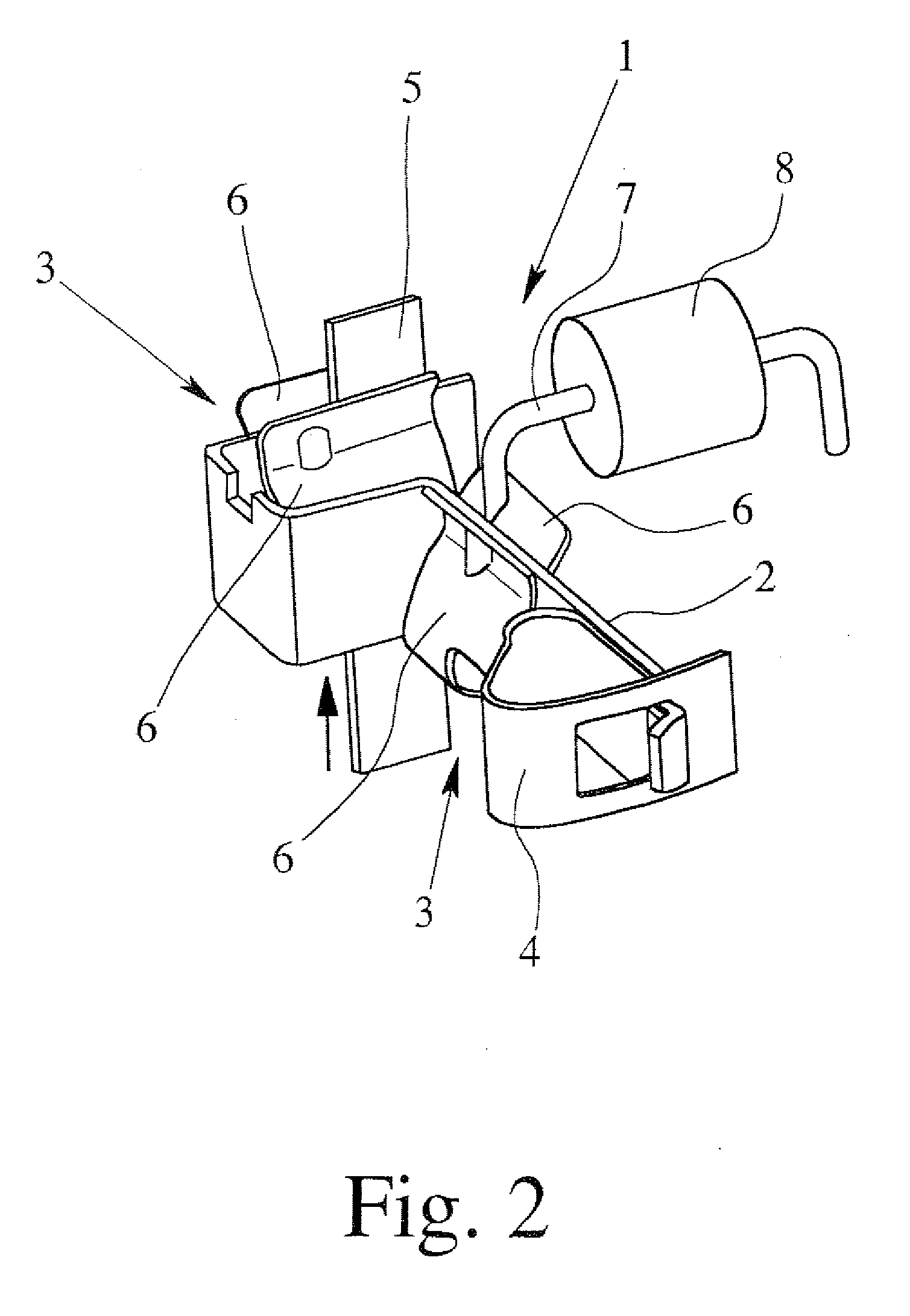
electrical junction box, the aforementioned object is achieved in a first alternative embodiment of the invention in that the clamping means for producing clamping contact between the connection device and the conductor strip is made and arranged such that at least one thin conductor strip routed out of the solar cell module can be inserted into the clamping means in two different opposing entry directions. Therefore, the invention takes a completely new approach in that thin conductor strips which are used for connection of the solar cells and which are routed out of the solar cell module of the invention can be inserted in two different preferably opposing entry directions into the clamping means, and thus, can be connected to the electrical connection device. The invention makes it possible, on the one hand, to insert the thin conductor strips being used to connect the solar cells from underneath, and on the other hand, to insert them into the clamping means from overhead. The invention thus avoids the complex procedure, known from the prior art, of routing the thin conductor strips for connecting the solar cell in the junction box first up, and then bending them by up to 180° in order to feed them to the connection device.
[0015] When the solar cells of the solar cell module are connected, the required effort is also greatly reduced by the invention. Therefore it is provided in accordance with the invention that, if necessary, a conductor strip can be inserted into the clamping means from one side of it or the other. Depending on the given arrangement of the connection device in the housing, it can be provided that the conductor strip be inserted into the clamping means in one entry direction or in the other. This yields far greater flexibility in the arrangement of the connection device in a junction box as claimed in the invention for a solar cell module. The junction box of the invention, moreover, further facilitates the connection of the thin conductor strips routed out of the solar cell module since the junction box can be placed on the solar cell module from two connection sides in order to insert the conductor strips from underneath into the electrical connection device.
[0017] For example, in the junction box, there can be a plurality of electrical connection devices which can be located preferably next to one another. In this case, it is possible to insert the first supply lead of an electronic component, preferably a bypass diode, into the clamping means of the first connection device and the second supply lead of the component into the clamping means of an adjacent, second connection device so that it is no longer necessary to arrange, for example, the bypass diodes on a circuit board, as is conventionally provided in the junction box known from the prior art. This leads to the free space available within the box for connecting the conductor strips being increased; this facilitates connection. Moreover, it is advantageous that the clamping means provided in the junction box in accordance with the invention can be connected, if necessary, to a conductor strip and / or to a supply lead of an electronic component; this leads to a simple structure of the junction box of the invention and to high flexibility in the arrangement of the connection device in the junction box as claimed in the invention.
[0018] In one especially preferred embodiment, it is provided that the clamping means is made Ω-shaped with two clamping legs which are connected via a bottom section which is located in the bottom area of the clamping means, which run onto one another in the direction to one clamping section of the clamping means, and which on the end pass into diverging entry bevels, so that the clamping means in the clamping section has an essentially X-shaped cross section. The Ω-shaped execution of the clamping means contributes to it being easily possible to insert a conductor strip and / or supply lead of an electronic component from overhead via entry bevels into the clamping section. Moreover, Ω-shaped clamping means can be easily produced and enable reliable electrical contact-making of the conductors which have been inserted into the clamping section.
[0023] The clamping legs and / or the bottom section can be produced from a spring material. This facilitates production and leads to low production costs. Basically, however, it is also possible for the terminal legs to the spring-mounted in order to make available sufficient clamping force in the area of the clamping section.

Problems solved by technology

However, a problem can arise when a solar cell module is partially shadowed, therefore a solar cell or individual solar cells of the solar cell module receive less or no solar radiation at all.
In contrast to shadowing of the solar module uniformly over its entire surface, which leads only to a reduction in output, the following problem arises with partial shadowing: A common current flows through the series-connected solar cells of the solar cell module, each individual solar cell with its respective voltage contributing to the total voltage of the solar cell module.
However, this means that the entire module can no longer deliver current, so that the overall operation of the solar cell module is adversely affected.
If the voltage on the shadowed solar cell is greater than its blocking voltage, a breakdown occurs in the solar cell, and thus, the solar cell is permanently damaged.
Even if the solar cell should not be damaged by the breakdown, a large power loss is converted in the shadowed solar cell so that the shadowed solar cell heats up.
This heating can also lead to damage to the shadowed solar cell and to the solar cells adjacent to it.
This results in that a shadowed solar cell no longer supplies a portion to the overall voltage of the solar cell module, but the current flow is nevertheless maintained.
In any case, this procedure is very complex and time-consuming, and connection faults cannot be easily avoided.
Moreover, in the known junction box, it is disadvantageous that, based on the limited external dimensions of the housing generally within the junction box, the electrical and / or electronic means and the connection device must be located very near one another.
For this reason, only a very small free space is available for connecting the conductor strips; this makes connection difficult.

Method used


Image

  • Electrical junction box for a solar cell module
  • Electrical junction box for a solar cell module
  • Electrical junction box for a solar cell module

Examples


Embodiment Construction

[0031] In FIG. 1, a preferred embodiment of a connection device 1 is shown which can be used to connect a junction box in accordance with the invention to a solar cell module the housing of the junction box being only schematically represented in phantom outline since the construction of the housing itself, apart from the provision of openings on additional sides. can be of any suitable construction and configuration known for junction boxes of this type. The connection device 1 has a current bar 2 and two clamping means 3 which are clamped onto the current bar 2. Fundamentally, more than two clamping means 3 can also be clamped onto the current bar 2. Moreover, the current bar 2 has a terminal 4 on a free end, and in this case, a tension spring terminal. In the installed state, the connection device 1 is located within the electrical junction box and is connected to the solar cell module via thin conductor strips 5.

[0032] In order to enable simple and reliable connection of the th...


PUM


Abstract

An electrical junction box for a solar cell module of solar cells which are connected with thin conductor strips, with a housing and electrical and / or electronic devices provided in the housing, and at least one electrical connection device (1) which has at least one terminal (3) and which is provided in the housing. The clamping mechanism (3) for producing clamping contact is made and arranged such that at least one thin conductor strip (5) routed out of the solar cell module can be inserted into the clamping mechanism in two different opposing entry directions. Thus, simple and reliable connection of thin conductor strips (5) routed out of the solar cell module can be guaranteed.

Description

BACKGROUND OF THE INVENTION [0001] 1. Field of the Invention [0002] The invention relates to an electrical junction box for a solar cell module of solar cells which are connected with thin conductor strips, with a housing and electrical and / or electronic means provided in the housing, and at least one electrical connection device which has at least one terminal means and which is provided in the housing. [0003] 2. Description of Related Art [0004] Since the output voltage of individual solar cells is generally too low to operate electrical devices, such as household appliances or similar devices, generally, several solar cells are interconnected to form solar cell modules. In this regard, on the one hand, there is the possibility of series connection of the solar cells, and on the other, the possibility of parallel connection of the solar cells in the solar cell module. The individual currents of the solar cells are added to one another to form the overall current by parallel connec...

Claims


Application Information

Patent Timeline
Patent Type & Authority Applications(United States)
IPC IPC(8): H02N6/00
CPCH01R4/4818H02S40/34H01R13/113Y02E10/50H01R4/48185
Inventor NIELECK, UDOQUARDT, DIRKWASSERFUHR, FRIEDELZBOROWSKI, ZBIGNIEWSCHMIDT, WIELANDSPELSBERG, HOLGER
Owner GUNTHER SPELSBERG GMBH CO
Why Eureka
Try Eureka