Sputtering target with slow-sputter layer under target material

a target material and sputtering technology, applied in the direction of electrolysis components, vacuum evaporation coatings, coatings, etc., can solve the problems of undesirable burn-through, uneven or non-uniform erosion of sputtering material from the tube, contamination of the sputtered film on the substrate, etc., to reduce the risk of burn-through, increase the utilization and/or lifetime of the target, and prevent or reduce the likelihood of burn-through

Inactive Publication Date: 2006-12-28
GUARDIAN GLASS LLC
View PDF18 Cites 12 Cited by
  • Summary
  • Abstract
  • Description
  • Claims
  • Application Information

AI Technical Summary

Benefits of technology

[0009] Certain example embodiments of this invention relate to a target for use in sputtering materials onto a substrate. In certain example embodiments, the target comprises a cathode tube with a slow sputtering material applied thereto prior to application of the target material to be sputtered onto the substrate. Thus, the slow sputtering material is located between the cathode tube and the material to be sputtered, with both the slow sputtering material and the material to be sputtered being supported by the cathode tube. The use of the slow sputtering material between the cathode tube and the material to be sputtered is advantageous in that this can reduce the risk of burn-through to the tube during sputtering (e.g., in the turn-around area of the target). In certain example embodiments, the use of the slow sputtering material may increase the target utilization and / or lifetime of the target.
[0010] The use of a thin layer of slow sputtering material (e.g., Ti) as a pre-coating for a cathode tube target is capable of preventing or reducing the likelihood of burn-through to or of the tube. An alternative can be to utilize the slow sputtering material as the material for making the cathode tube. In either case, target materials to be sputtered (e.g., Sn, Zn, etc.) can be applied over the slow sputtering material. When the target material to be sputtered has been consumed by sputtering, especially in the turn-around region of the cathode, the slow sputtering material can protect the target tube from burn-through. In certain example embodiments, the slow sputtering material may extend along the entire, or substantially the entire, length of the target tube, and / or is not exposed during normal sputtering operations.
[0011] In certain other example embodiments of this invention, a layer or coating of non-conductive material (e.g., an oxide of Si, Sn, Zn, etc.) provided on the cathode tube 2 (only in the dogbone section) can be used to protect against burn-through. This non-conductive material, located in the dogbone section of the target, is effective in that the etching pattern (sputtering) will slow down or substantially stop at the non-conductive material when the target material in that area is consumed since the surface charge will prevent or reduce sputtering ions such as Ar+ bombardment, especially when a DC, pulse DC or middle frequency AC power supply is used for sputtering. While this could cause an increase in micro-arcing (not big hard arcs) when the non-conductive material is exposed during sputtering, this micro-arcing should not significantly affect coating the product but instead could be advantageous in that it can give an operator a signal or indication as to how much of the target life is left (e.g., it is time to replace the target, or soon will be). In different example embodiments of this invention, the non-conductive layer can be applied either only in the dogbone section, or alternatively over the entire length of the target tube (e.g., when an rf power supply is used for puttering).

Problems solved by technology

While rotating magnetron sputtering targets represent an improvement with respect to erosion, they can still experience uneven or non-uniform erosion of the sputtering material from the tube during sputtering—especially at the high sputtering rate areas proximate the target ends which are sometimes called turn-around areas / portions.
Unfortunately, the uneven sputtering of the target material off of the cathode tube can result in undesirable burn-through.
Burning through the target material to the tube would result in the sputtering of material making up the tube (e.g., stainless steel) thereby resulting in contamination of the sputtered film on the substrate.
Thus, it will be appreciated that burn-through represents a significant problem.

Method used


Image

  • Sputtering target with slow-sputter layer under target material
  • Sputtering target with slow-sputter layer under target material
  • Sputtering target with slow-sputter layer under target material

Examples


Embodiment Construction

[0016] Referring now more particularly to the accompanying drawings in which like reference numerals indicate like parts throughout the several views.

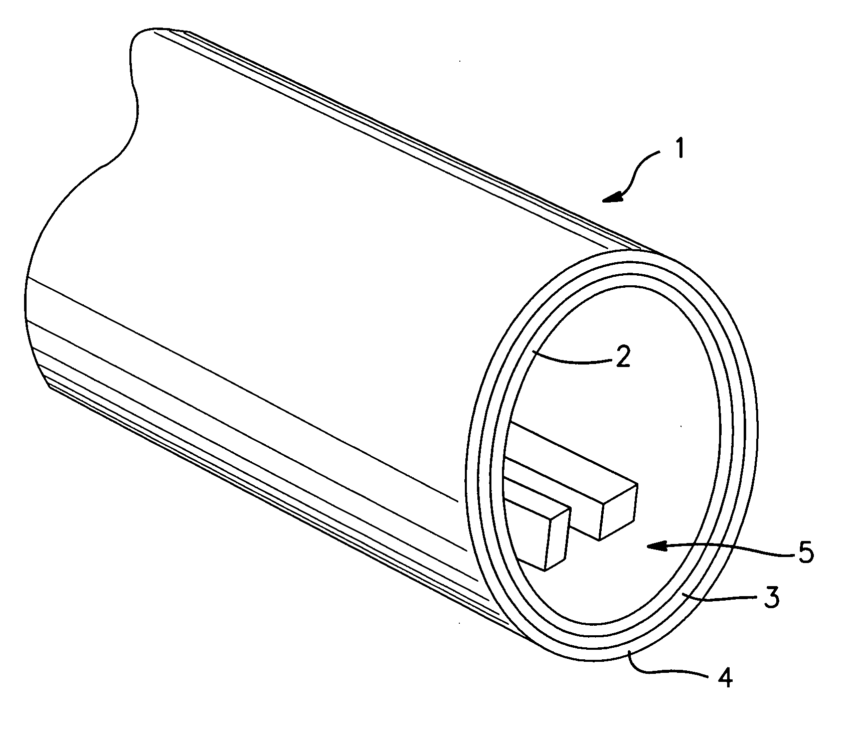
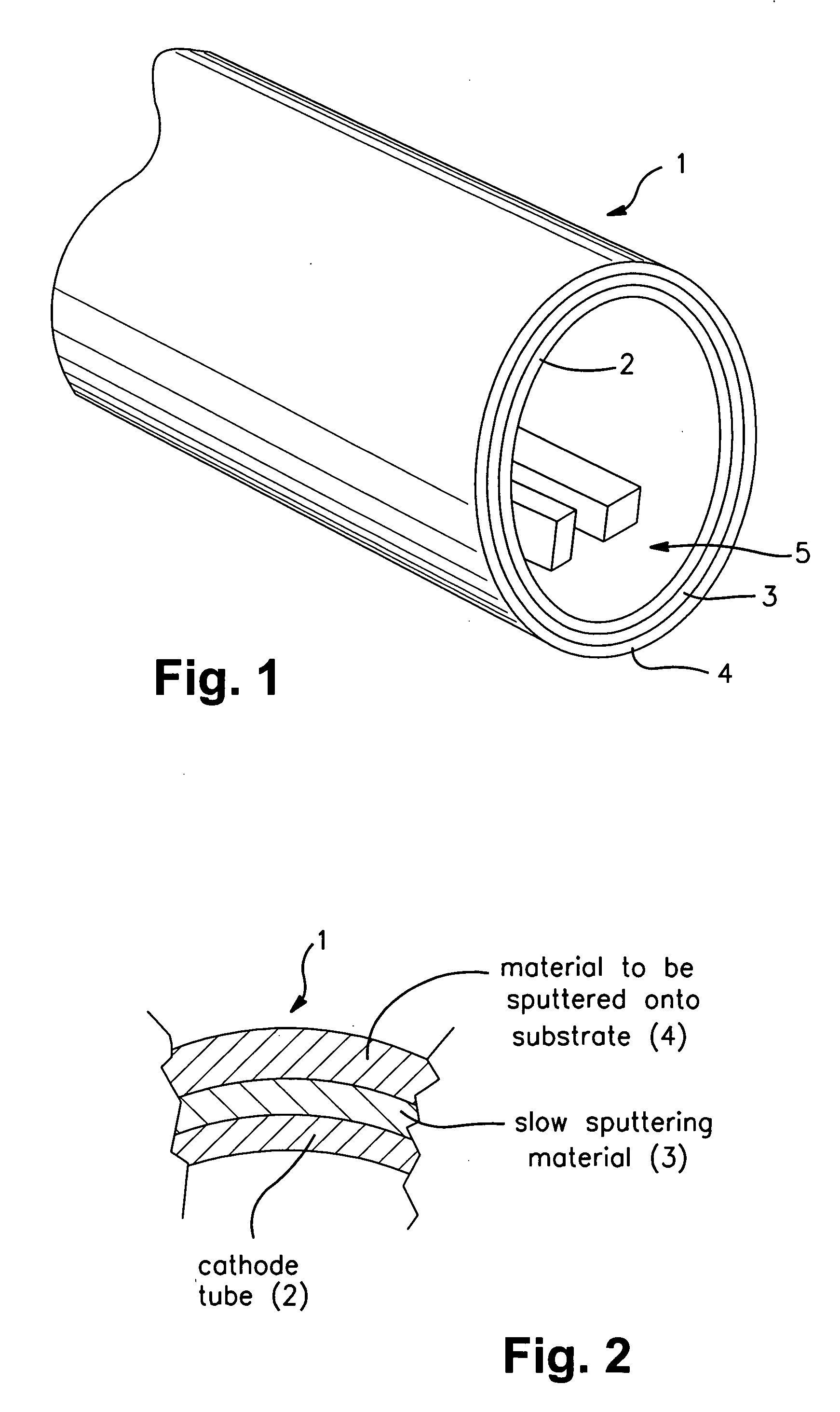
[0017]FIGS. 1-2 illustrate an example sputtering target according to an example non-limiting embodiment of this invention, with FIG. 2 being a cross-sectional view of a part of the target of FIG. 1. The illustrated cylindrical rotating target 1 includes a cathode tube 2 with a slow sputtering material 3 applied thereto prior to application of the target material 4 to be sputtered onto the substrate. Thus, the slow sputtering material 3 is on the tube 2, and is located between the cathode tube 2 and the target material 4 to be sputtered. Both the slow sputtering material 3 and the material 4 to be sputtered are on and supported by the cathode tube 2. Materials 3 and 4 may be formed on the tube 2 in any suitable manner (e.g., via plasma spraying). The use of the slow sputtering material 3 between the cathode tube 2 and the material 4 to...


PUM

PropertyMeasurementUnit
thicknessaaaaaaaaaa
thicknessaaaaaaaaaa
thicknessaaaaaaaaaa

Abstract

Certain example embodiments of this invention relate to a sputtering target(s) for use in sputtering material(s) onto a substrate. In certain example embodiments, the target includes a cathode tube with a slow sputtering material applied thereto prior to application of the target material to be sputtered onto the substrate. Because the slow sputtering material is located between the cathode tube and the material to be sputtered, the likelihood of burn-through can be reduced. In certain instances, target utilization and/or lifetime may be increased. In certain other example embodiments, a non-conductive layer may be provided proximate end portion(s) of the target between the cathode tube and the target material in order to reduce or prevent sputtering of material once the target material has been sputtered off such portion(s).

Description

[0001] This invention relates to a target for use in sputtering (e.g., magnetron sputtering). In certain example embodiments, the cathode tube of the target is coated with a slow sputtering material prior to applying the target material to the tube. Thus, the slow sputtering material is located between the tube itself and the target material. This can reduce or eliminate the risk of burn-through during sputtering, particularly in the turn around area, and / or which may increase the target utilization and / or lifetime in certain example instances. BACKGROUND OF THE INVENTION [0002] Sputtering is known in the art as a technique for depositing layers or coatings onto substrates. For example, a low-emissivity (low-E) coating can be deposited onto a glass substrate by successively sputter-depositing a plurality of different layers onto the substrate. As an example, a low-E coating may include the following layers in this order: glass substrate / SnO2 / ZnO / Ag / ZnO, where the Ag layer is an IR r...

Claims


Application Information

Patent Timeline
Patent Type & Authority Applications(United States)
IPC IPC(8): C23C14/00
CPCC23C14/3407H01J37/3435H01J37/3429H01J37/3405
Inventor MAYER, RAYMOND M.LU, YIWEI
Owner GUARDIAN GLASS LLC
Why Eureka
Try Eureka