
Nuclear Threat Detection

a nuclear threat and detection technology, applied in the field of threat detection, can solve the problems of large radiation emissions of human undergoing nuclear medicine imaging or radiation treatment using implanted radioactive seeds, difficult screening in practice, and large environmental radiation of gamma rays and neutrons, so as to improve the ability to identify the spectral signature, reduce background radiation, and increase the reliable threat detection of the system

Inactive Publication Date: 2006-12-28
INBAR DAN
View PDF99 Cites 24 Cited by
  • Summary
  • Abstract
  • Description
  • Claims
  • Application Information

AI Technical Summary

Benefits of technology

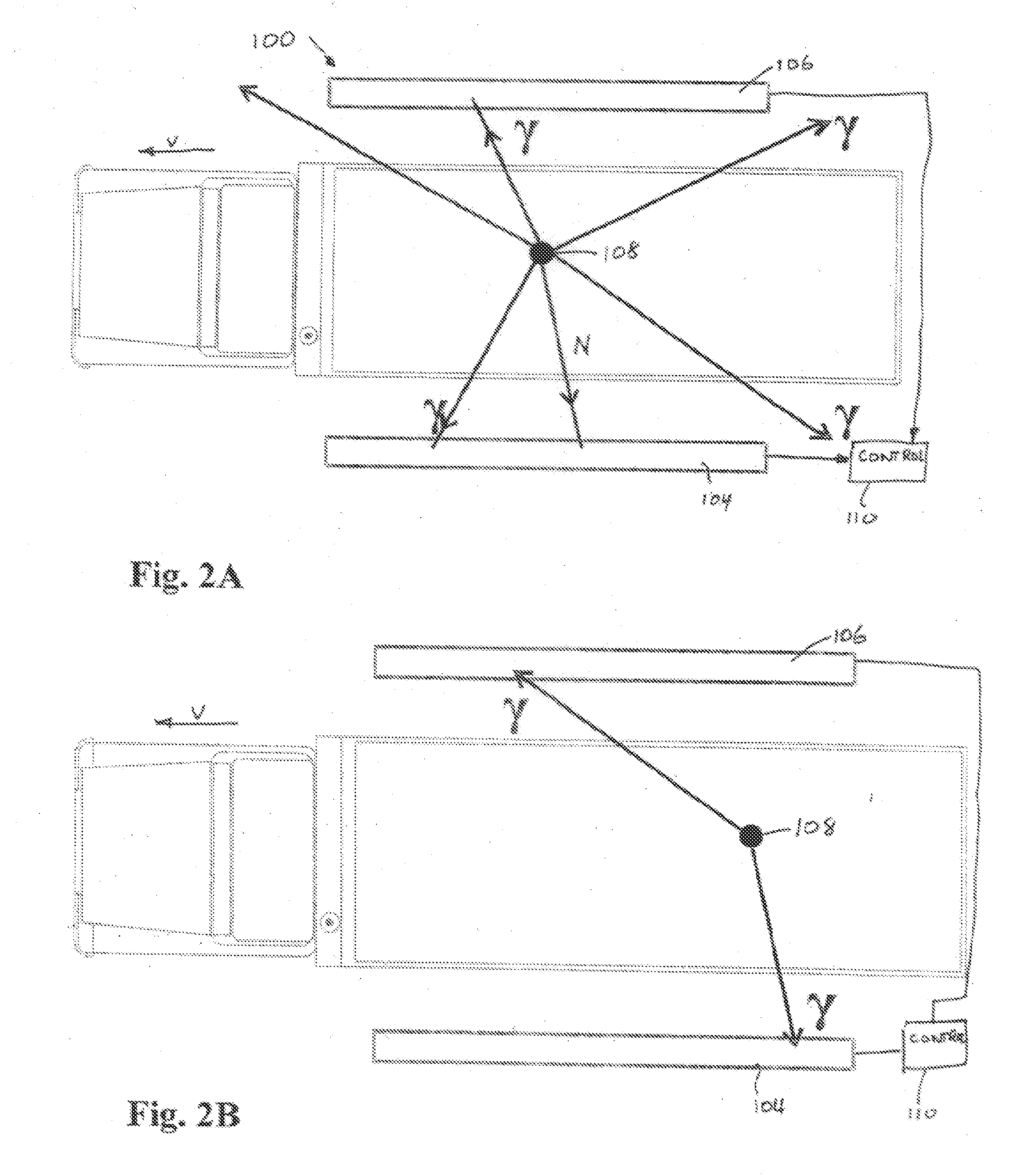
[0024] Alternatively or additionally, gross direction capability for both incident gammas and neutrons is achieved even without collimators. As to gamma rays, the incident gamma rays produce a number of scintillations as they travel through the detector segments. The side of the detector, the 2D positions facing the screened item, sub-nanosecond event times, and deposited energy of these scintillations are determined, and a gross direction of incidence of the gamma ray is estimated from analysis of positions of the first and second scintillations. This methodology is especially useful in reducing terrestrial and atmospheric radiation by a veto on particles that most probably come from a direction other than the direction of the screened object. As to neutrons, it is possible to determine if the neutrons entered the detector from the top, sides, front side facing the screened object or rear side facing to screened object, since neutrons of typical WgP spontaneous fission energies are captured within the first 5-10 cm of OS detector material. This enables the rejection of more than a half the environmental neutron radiation and an increase in selectivity (e.g., improved ROC) of the system.
[0124] There is further provided a method of SNM detection comprising screening a suspected item by placing it before at least one detector while the item is stationary to increase the number of radiation events captured by the detector.

Problems solved by technology

Such screening is difficult in practice due, at least in part, to the environment in which it is done.
Firstly, environmental radiation (including terrestrial and atmospheric radiation) of gamma rays and neutrons is substantial.
Additionally, humans undergoing nuclear medicine imaging or radiation treatment using implanted radioactive seeds can emit sizeable amounts of radiation.
These and other “natural” or “benign” sources of radiation: this phenomena coupled with the ability to shield the SNM and RDD, make simple detection schemes either ineffective in finding nuclear radiological threats or prone to a poor receiver operating characteristic (ROC), for example a large percentage of false positives.
Substantial numbers of false positives produce a large number of vehicles that have to be searched or otherwise vetted manually, making such simple systems practically useless for screening large numbers of vehicles.
ASP systems do not provide nuclear imaging of either gamma rays or neutrons.
ASP systems detection performance is limited primarily due to the high cost of NaI detectors, which limits the system detection area / sensitivity.
This limits the detection sensitivity.
Having only a single signature makes the system less reliable.
In addition, ASP systems do not provide several other SNM-RDD signatures such as 1D, 2D and 3D nuclear imaging, temporally based signatures such as cascade isotopes (e.g. Co60) doublets detection and gamma / neutron salvo emanating from spontaneous fission of SNM.
On the other hand, there is a common belief in the prior art that organic scintillators, although some non-spectroscopic OS based portals have been used in the past, fail to provide acceptable ROC as they do not provide energy resolution (or at best a very limited one) in the context of nuclear threat detection.
Furthermore, it is accepted that for all practical purposes screening portals organic scintillators have a poor gamma efficiency or “stopping power” at energies above 300 keV as compared to NaI(Tl).
In recent studies related to anti-neutrino detection (see http: / / arxiv.org / ftp / physics / papers / 404 / 0404071.pdf) (see F. Suekane et al., “An overview of the KamLAND 1; K-RCNP International School and mini-Workshop for Scintillating Crystals and their Applications in Particle and Nuclear Physics Nov., 17-18, 2003, KEK, Japan, it has been shown that extremely large (8 meter diameter) expensive (>$100 million, due mainly to the very large detector size and large number of large [18″] photomultiplier tubes (PMTs) used) liquid scintillator detectors can provide gamma energy resolution which is close to that of NaI(Tl).
Such devices are not practical for large scale (or even small scale) deployment for threat detection due to their geometry and astronomical cost.

Method used


Image

  • Nuclear Threat Detection
  • Nuclear Threat Detection
  • Nuclear Threat Detection

Examples


Embodiment Construction

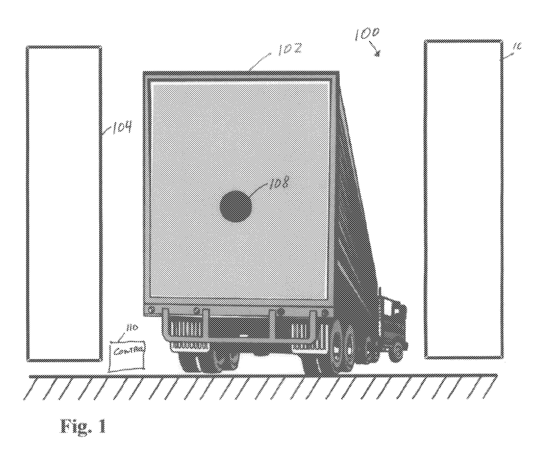
[0177]FIG. 1 shows a schematic drawing of a portion of a system 100 for detecting nuclear threats. As illustrated, vehicles 102, for example a truck, pass between two detectors 104, 106. In some embodiments only a single detector is used and in some, as described below, three or more such detectors are used. In a preferred embodiment of the invention, the detectors are of one of the types of detectors described below. The detectors are optionally high enough to cover the entire height of the truck or other objects being scanned. The length of the detector (in the direction of motion of the vehicle) is not related to the height; however in some embodiments of the invention it is made 3, 4, 6 or more meters long, so as to provide a desired detection sensitivity.

[0178] For illustration purposes, vehicle 102 is shown carrying a nuclear material 108.

[0179] A controller 110 receives signals from the detectors and based on these signals, and optionally on information regarding the speed ...


PUM


Abstract

A detector for detecting radiation, the detector comprising: a plurality of elongate scintillator segments arranged in a side by side array; and at least one pair of light sensors optically coupled to ends of each of the elongate scintillator such that they receive light from scintillations produced in the scintillator and generate electrical signals responsive thereto.

Description

RELATED APPLICATIONS [0001] The present application is a continuation in part of U.S. patent application Ser. No. 11 / 348,040 filed Feb. 6, 2006, which claims the benefit under 35 U.S.C. §1.19(e) of U.S. Provisional Application 60 / 649,541 filed Feb. 4, 2005; 60 / 651,622 filed Feb. 11, 2005; 60 / 654,964 filed Feb. 23, 2005. This application also claims the benefit under 35 U.S.C. §1.19(e) of US Provisional Applications: 60 / 706,013 filed Aug. 8, 2005; 60 / 706,752 filed Aug. 10, 2005; 60 / 707,154 filed Aug. 11, 2005; 60 / 709,428 filed Aug. 19, 2005; 60 / 710,891 filed Aug. 25, 2005; 60 / 596,769 filed Oct. 20, 2005; 60 / 596,814 filed Oct. 24, 2005; 60 / 597,354 filed Nov. 28, 2005; 60 / 597,434 filed Dec. 1, 2005; 60 / 597,435 filed Dec. 1, 2005, 60 / 597,569 filed Dec. 10, 2005; 60 / 597,629 filed Dec. 14, 2005; and 60 / 767,379 filed Mar. 23, 2006. The disclosures of all applications are incorporated herein by reference.FIELD OF THE INVENTION [0002] The present invention is in the field of threat detection...

Claims


Application Information

Patent Timeline
Patent Type & Authority Applications(United States)
IPC IPC(8): G01T1/20
CPCG01T1/167G01V5/0091G01V5/0075G01T1/20G01V5/26G01V5/281
Inventor INBAR, DAN
Owner INBAR DAN
Learn More