Methods and Apparatus for Improved Gamma Spectra Generation

a technology of gamma spectra and gamma neutrons, applied in the field of threat detection, can solve the problems of large radiation emission of human undergoing nuclear medicine imaging or radiation treatment using implanted radioactive seeds, difficult screening in practice, and increase the reliability of threat detection of the system, so as to reduce background radiation, improve the detection effect, and improve the detection effect of signal

Inactive Publication Date: 2007-08-16
INBAR DAN
View PDF99 Cites 36 Cited by
  • Summary
  • Abstract
  • Description
  • Claims
  • Application Information

AI Technical Summary

Benefits of technology

[0038] Another advantage of large detectors, especially imaging detectors, is the amount of time each portion of a moving vehicle is screened. Taking into account the movement of the vehicle, every portion of the moving vehicle stays within range longer and provides a better detected signal.
[0039] Some embodiments of the detectors can identify the general or gross direction of an incident gamma and / or neutron particle independent of the use of a collimator and / or shielding. In an embodiment of the invention, at least some events that are incident from a direction other than a direction from which they are expected when screening an object, can be rejected. This allows for a decrease in background radiation both from environmental radiation and from radiation emanating from other objects (e.g. nuclear medicine patients outside the field of screening). In addition, it enables the rejection of events that enter from the back, sides, top and bottom of the detector. Rejecting events that do not come from the expected direction can increase the reliable threat detectability of the system many fold.
[0040] Some systems utilizing the detectors provide one or a plurality of energy windowed images on an isotope-by-isotope basis. This technique is used in nuclear medicine imaging applications to provide maps of individual isotopes. Providing maps for different isotopes in threat detectors improves the image and its point source contrast over the background radiation. The efficacy of such windowing is improved by the methods of the present invention.
[0041] Organic scintillator with which the present invention may be used may have both intrinsic spatial and temporal resolution and spectrographic properties to discriminate between isotopes. In an embodiment of the invention, the presence of escape quanta can be detected for a given incident particle, and the event vetoed. This can provide a significant improvement in spectroscopic isotope identification.
[0042] The combination of high light detection efficiency and high and uniform collection efficiency associated with loci dependent light collection variation correction and the small rate of escape quanta (due to the large detector) allows for gamma spectroscopic isotope I.D. that is similar to that of detectors with NaI(Tl) scintillators. It should be noted that the exact design of the detector is dependent on a tradeoff between gamma spectroscopic identification and imaging capability. If imaging capability is desired, then some kind of collimation may be required. This reduces the capture efficiency based threat signatures performance. On the other hand, if high particle collection efficiency is desired, for spectroscopy, and temporal coincidence signatures (e.g. cascading isotopes I.D. spontaneous fission gamma / neutron I.D.) detection (discussed below) having no collimators may be preferable, to maximize overall sensitivity. In some embodiments, a combination of areas that have collimation and areas that do not have collimation provide a compromise design. Such embodiments are discussed herein.
[0043] It is noted that gamma rays give up their energy inside an organic scintillator material in a series of time and geometrically spaced events (e.g. Compton interactions), each of which produces a separate scintillation. In general, it is preferred to have the size of the segments matched to a mean length between scintillations (this indicates a compromise between low [100 keV gammas having a short distance] and high energy gammas [2.6 MeV having a long distance]), such that the position of each event in the detector is, with high probability, in a different segment. The time constant of a single scintillation is the same order of magnitude (a few nanosec) as the time between scintillations of the same event, hence they can not easily be discriminated from each other by time if they occur inside one measurement channel. If, however, they occur in different segments, their leading edge timestamp, deposited energy and 2D location are separately detected and measured. This allows the use of algorithms used in Compton imaging techniques to detect the gross directionality of the incident gamma, and also allows rejection of gammas that are incident from the back face and to a great extent terrestrial and atmospheric gammas and neutrons.

Problems solved by technology

Such screening is difficult in practice due, at least in part, to the environment in which it is done.
Firstly, environmental radiation (including terrestrial and atmospheric radiation) of gamma rays and neutrons is substantial.
Additionally, humans undergoing nuclear medicine imaging or radiation treatment using implanted radioactive seeds can emit sizeable amounts of radiation.
These and other “natural” or “benign” sources of radiation coupled with the ability to shield (using high Z materials like lead to shield gammas and some low Z materials to shield neutrons) the SNM and RDD, make simple detection schemes either ineffective in finding nuclear radiological threats or prone to a poor receiver operating characteristic (ROC), for example by having a large percentage of false positives.
Substantial numbers of false positives (also called ‘false alarms’) produce a large number of screened objects (e.g. vehicles, people, cargo) that have to be searched or otherwise vetted manually, making such simple systems practically useless for screening large numbers of objects.
ASP systems do not provide nuclear imaging, of either gamma rays or neutrons.
ASP systems detection performance is limited primarily due to the high cost of NaI detectors, which limits the system detection area / sensitivity.
Because of the high price and practical cost constraints of the NaI(Tl) and He-3 detectors, their number is small [typically the ASP NaI detectors have a sensitive area of 0.64 meter2] relative to the distance from the threat radiation source, resulting in a small solid angle of the detector as viewed by the threat.
This limits the detection sensitivity and selectivity.
Having only one or two signature detection capabilities makes the system less reliable.
In addition, ASP systems do not provide several other SNM-RDD signatures such as 1D, 2D and 3D nuclear imaging, temporally based signatures such as cascade isotopes (e.g. Co60) doublets detection and gamma / neutron salvo emanating from spontaneous fission of SNM.
On the other hand, there is a common belief in the prior art that organic scintillators, although some non-spectroscopic OS based portals have been used in the past, fail to provide acceptable ROC as they do not provide energy resolution (or at best a very limited one) in the context of nuclear threat detection.
Furthermore, it is accepted that for all practical purposes screening portals organic scintillators have a poor gamma efficiency or “stopping power” at energies above 300 keV as compared to NaI(Tl).
Such devices are not practical for large scale (or even small scale) deployment for threat detection due to their geometry and astronomical cost.

Method used


Image

  • Methods and Apparatus for Improved Gamma Spectra Generation
  • Methods and Apparatus for Improved Gamma Spectra Generation
  • Methods and Apparatus for Improved Gamma Spectra Generation

Examples


Embodiment Construction

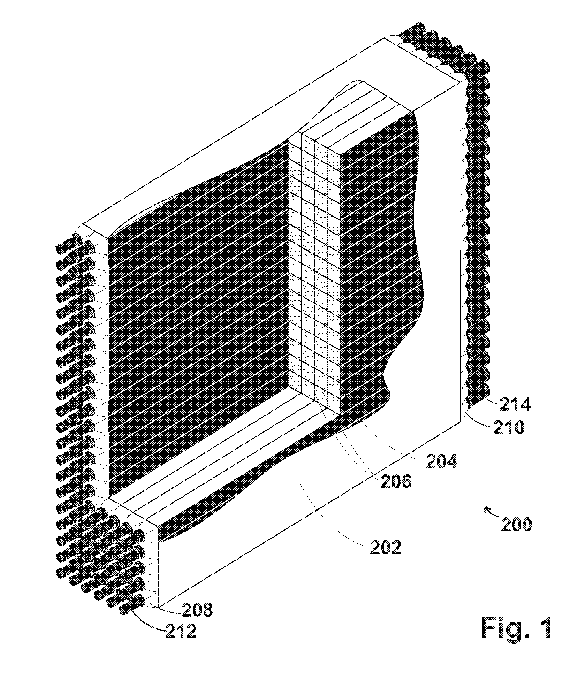
[0063]FIG. 1, corresponding to FIG. 3 of US Publication 2006 / 0289775, shows a partial cut-away view of a segmented detector 200 (corresponding to detectors 104 and 106 of FIG. 1 of US Publication 2006 / 0289775, in an embodiment of the invention). In the following discussion, the visible face of the detector is referred to as a front face 202 and the other face, as the rear face.

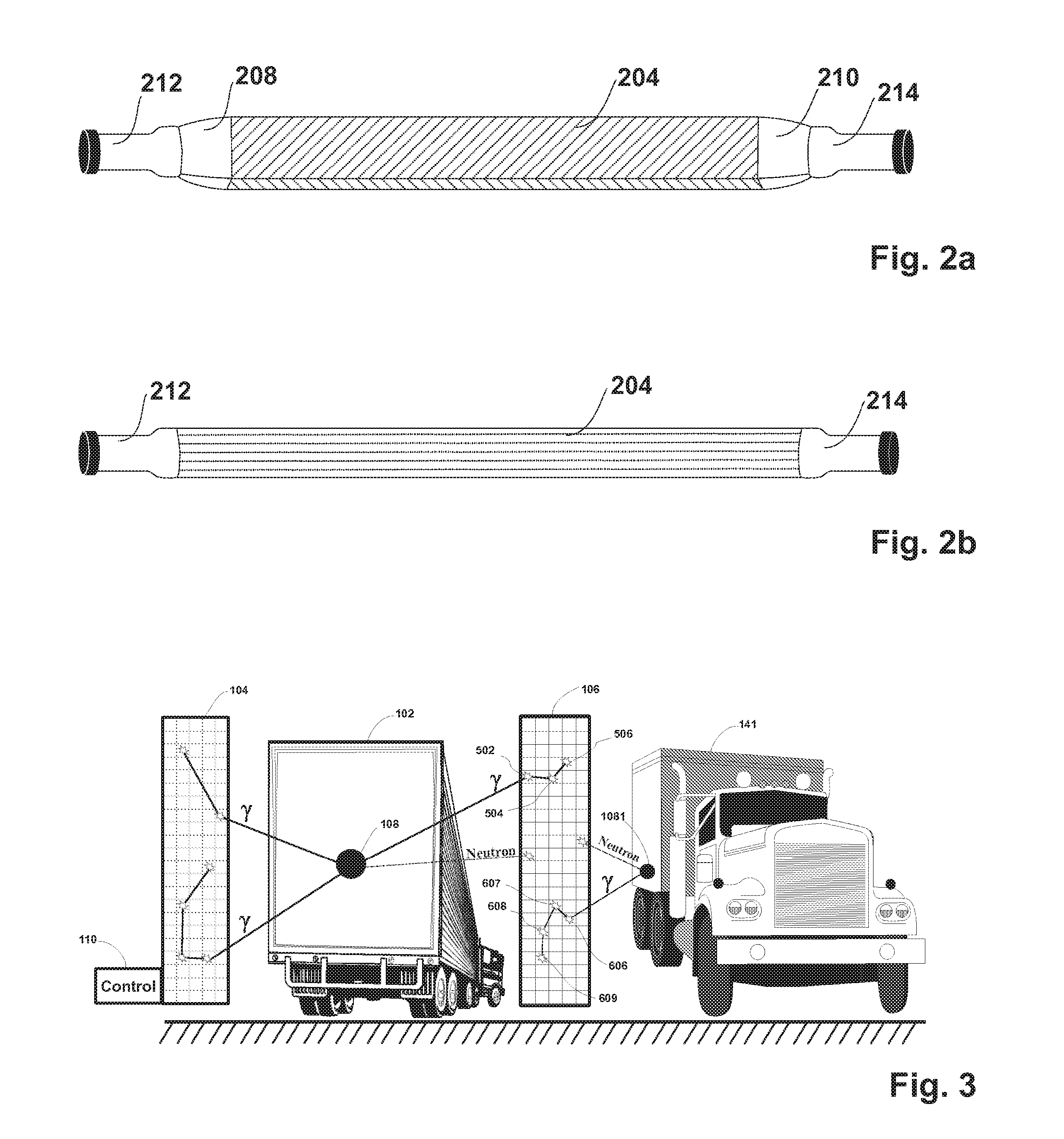
[0064] As shown in the exemplary embodiment of FIG. 1 and referring also to FIG. 2A, corresponding to FIG. 4A of US Publication 2006 / 0289775, detector 200 is segmented into elongate segments of scintillation material (one of which is referenced with reference numeral 204) by reflective partitions 206. Thus, light from a scintillation which occurs in a particular segment is reflected from the partitions and remains in the same segment. By the nature of the reflections, the light is reflected toward one or the other end of the elongate segment, where it is optionally concentrated by a light concentrator before ...


PUM


Abstract

A method of improving energy determination of a Gamma event which interacts with a segmented scintillation detector, the method comprising: identifying radiation events detected by a detector that are likely not to have deposited their full energy in the detector, based only on characteristics of said detected events; and treating the identified radiation events differently from other radiation events that are likely to have deposited their full energy in the detector.

Description

RELATED APPLICATIONS [0001] The present application is a continuation in part of U.S. patent application Ser. No. 11 / 463,112 filed Aug. 8, 2006 (published Dec. 28, 2006 as US Patent Publication 2006 / 0289775) and claims the benefit under 35 U.S.C. §1.19(e) of U.S. Provisional application, 60 / 767,379 filed Mar. 23, 2006, 60 / 891551 filed Feb. 26, 2007, 60 / 891727 filed Feb. 27, 2007, 60 / 891729 filed Feb. 27, 2007, 60 / 891738 filed Feb. 27, 2007, 60 / 891751 filled Feb. 27, 2007, 60 / 892254 filled Mar. 1, 2007 and 60 / 892893 filled Mar. 5, 2007. U.S. patent application Ser. No. 11 / 463,112 is a continuation in part of U.S. patent application Ser. No. 11 / 348,040 filed Feb. 6, 2006 (published Dec. 28, 2006 as US Patent Publication 2006 / 0284094), which claims the benefit under 35 U.S.C. §1.19(e) of U.S. Provisional Applications 60 / 649,541 filed Feb. 4, 2005; 60 / 651,622 filed Feb. 11, 2005; 60 / 654,964 filed Feb. 23, 2005. This application also claims the benefit under 35 U.S.C. §1.19(e) of U.S. Pr...

Claims


Application Information

Patent Timeline
Patent Type & Authority Applications(United States)
IPC IPC(8): G01T1/20
CPCG01V5/0091G01T1/167
Inventor BEER, STEVEINBAR, DAN
Owner INBAR DAN
Why Eureka
Try Eureka