Immersion lithography with equalized pressure on at least projection optics component and wafer

Inactive Publication Date: 2006-12-28
GLOBALFOUNDRIES INC
View PDF21 Cites 11 Cited by
  • Summary
  • Abstract
  • Description
  • Claims
  • Application Information

AI Technical Summary

Benefits of technology

[0007] The invention solves the above-described problems, inter alia, by providing an immersion lithography apparatus and method, and a lithographic optical column structure are disclosed for conducting immersion lithography with at least the projection optics of the optical system and the wafer in different fluids at the same pressure. In particular, an immersion lithography apparatus is provided in which a supercritical fluid is introduced about the wafer, a

Problems solved by technology

Unfortunately, the extension of immersion lithography to 157 nm wavelengths is complicated by the lack of transparent liquid media that can be used as a liquid immersion material, e.g., water absorbs 157 nm light.
Other challenges to this approach include prevention of bubbles in the liquid during e

Method used


Image

  • Immersion lithography with equalized pressure on at least projection optics component and wafer
  • Immersion lithography with equalized pressure on at least projection optics component and wafer
  • Immersion lithography with equalized pressure on at least projection optics component and wafer

Examples


Example

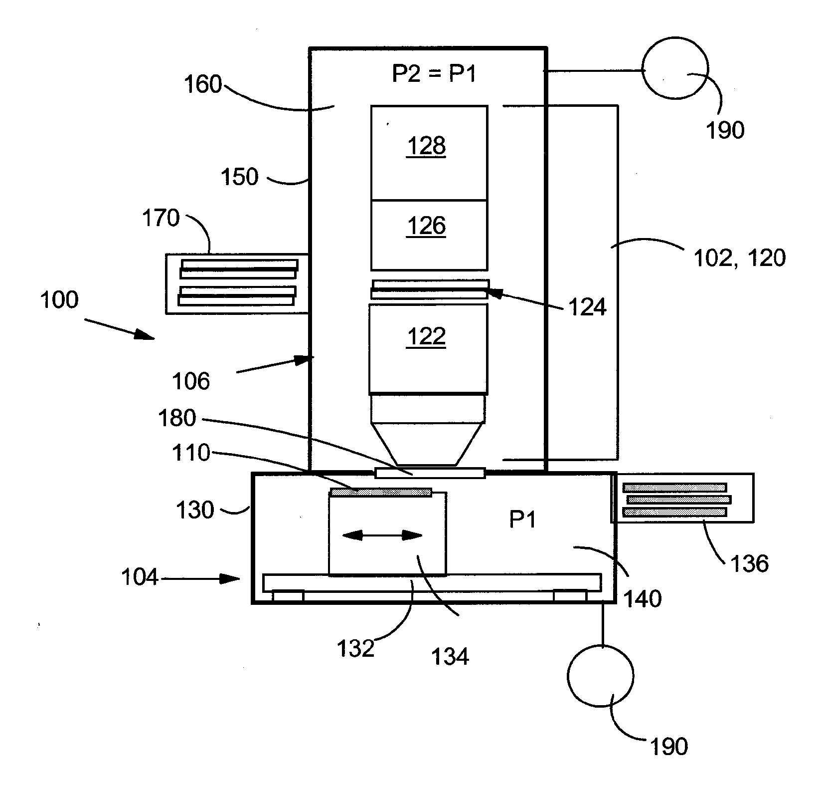
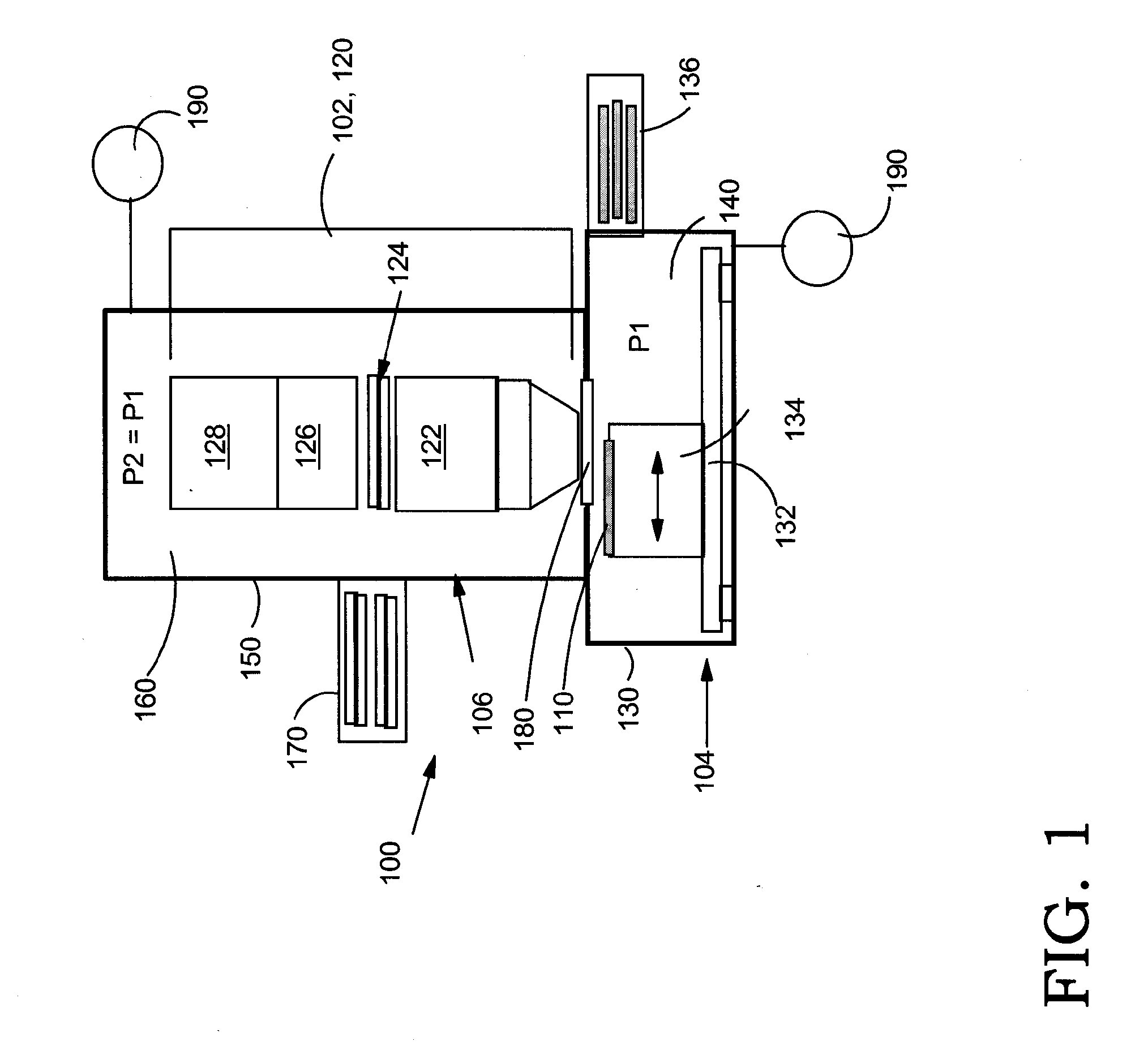
[0017] With reference to the accompanying drawings, FIG. 1 illustrates a first embodiment of an immersion lithography apparatus 100 according to the invention. Apparatus 100 includes a lithographic optical column structure 102, which will be described along with apparatus 100. As shown in FIG. 1, apparatus 100 includes a first chamber 104 and a second chamber 106. First chamber 104 is adapted for holding a wafer 110 to be irradiated with any now known or later developed optical system 120 for projecting radiation onto wafer 110. An illustrative optical system 120 may include, inter alia, projection optic component 122, a mask 124, condenser 126 and illuminator 128. First chamber 104 also includes conventional automated wafer support structure such as an enclosure 130, a wafer table 132, a wafer stage 134, and a load lock 136. Load lock 136 may include conventional structure such as gate valves, support table, transfer robot, etc., for allowing ingress / egress of wafer(s) 110.

[0018] ...

Example

[0024] Referring to FIGS. 3-4, alternative third and fourth embodiments of the invention will now be described. As shown in FIGS. 3-4, a third and fourth embodiment includes an immersion lithography apparatus 200, 300, respectively, including all of the structure of apparatus 100 (FIG. 1), except that only one chamber 204 is provided to enclose wafer 110, i.e., no window 180 (FIGS. 1-2). In FIGS. 3-4, at least projection optic component 122 of optical system 120 is enclosed in chamber 204 for projecting radiation onto wafer 110. FIG. 3 illustrates an embodiment in which all of optical system 120 is enclosed in chamber 204. In this case, a load lock 270, as described above, for chamber 204 to allow ingress / egress of a mask 124 of optical system 120 is provided. FIG. 4 illustrates an embodiment in which only projection optic component 122 of optical system 120 is enclosed in chamber 204. In this case, load lock 270 (FIG. 3) is not necessary, but a pressure- resistant window 282 to all...


PUM


Abstract

An immersion lithography apparatus and method, and a lithographic optical column structure are disclosed for conducting immersion lithography with at least the projection optics of the optical system and the wafer in different fluids at the same pressure. In particular, an immersion lithography apparatus is provided in which a supercritical fluid is introduced about the wafer, and another fluid, e.g., an inert gas, is introduced to at least the projection optics of the optical system at the same pressure to alleviate the need for a special lens. In addition, the invention includes an immersion lithography apparatus including a chamber filled with a supercritical immersion fluid and enclosing a wafer to be exposed and at least a projection optic component of the optical system.

Description

BACKGROUND OF THE INVENTION [0001] 1. Technical Field [0002] The present invention relates generally to semiconductor fabrication, and more particularly, to an immersion lithography apparatus and method, and a lithographic optical column structure for conducting immersion lithography with at least the projection optics of the optical system and the wafer under the same pressure. [0003] 2. Related Art [0004] The ongoing pursuit of fabricating smaller semiconductor devices has currently caused the semiconductor fabrication industry to pursue advancements relative to immersion photolithography rather than dry photolithography. For example, the current focus in the industry has shifted from dry 157 nanometer (nm) wavelength lithography technology to immersion (wet) 193 nm wavelength lithography technology, with the objective to achieve immersion photolithography at 157 nm. Immersion photolithography approaches include filling a space between the last projection lens and the wafer in a l...

Claims


Application Information

Patent Timeline
IPC IPC(8): G21G5/00
CPCG03F7/70341
Inventor FURUKAWA, TOSHIHARUHAKEY, MARK C.HOLMES, STEVEN J.HORAK, DAVID V.MITCHELL, PETER H.
Owner GLOBALFOUNDRIES INC
Why Eureka
Try Eureka