Clock generating circuit and clock generating method

a clock generation and clock technology, applied in the direction of angle modulation, pulse automatic control, electrical apparatus, etc., can solve the problems of increased circuit configuration, delay in data transmission, and inability to so as to reduce the influence of delay time and securely carry out data transmission

Active Publication Date: 2006-12-28
MONTEREY RES LLC
View PDF4 Cites 15 Cited by
  • Summary
  • Abstract
  • Description
  • Claims
  • Application Information

AI Technical Summary

Benefits of technology

[0014] In the clock generating circuit according to the invention, an output clock signal is delayed on the basis of a phase difference signal. Therefore, in comparison with a case where a fluctuation of the cycle of the output clock signal is detected, it is possible to detect fluctuations in the frequency and cycle of the output clock signal at a further early timing, and it is possible to reflect the fluctuations in frequency of the output clock signal onto the delay unit at a high speed. That is, in comparison with the case of the background art in which fluctuations in frequency of the output clock signal are fed back, influence of the delay time can be reduced.
[0015] Accordingly, by utilizing the clock generating circuit according to the invention for the above-described synchronous interface in which accuracy of the phase difference of the respective clock signals is requested, it is possible to further securely carry out data transmission.

Problems solved by technology

In the clock generating circuit according to Japanese Unexamined Patent Publication No. 2005-20083, since a DDL (Delay Lock Loop) is utilized for the comparison, the circuit is complicated, resulting in an increase in the circuit configuration.
In addition, since the fluctuation range of the delay time in the delay element is adjusted by feedback control of the DLL, a delay in response to frequency fluctuations of the output clock signal occurs.
Where the clock generating circuit according to Japanese Unexamined Patent Publication No. 2005-20083 is utilized for the above-described synchronous interface, such a problem occurs, by which there is a risk that data transmission is not securely carried out.

Method used


Image

  • Clock generating circuit and clock generating method
  • Clock generating circuit and clock generating method
  • Clock generating circuit and clock generating method

Examples


Embodiment Construction

[0029] Hereinafter, a detailed description is given of an embodiment that is one detailed example of a semiconductor apparatus according to implementation of the invention with reference to FIG. 1 through FIG. 10.

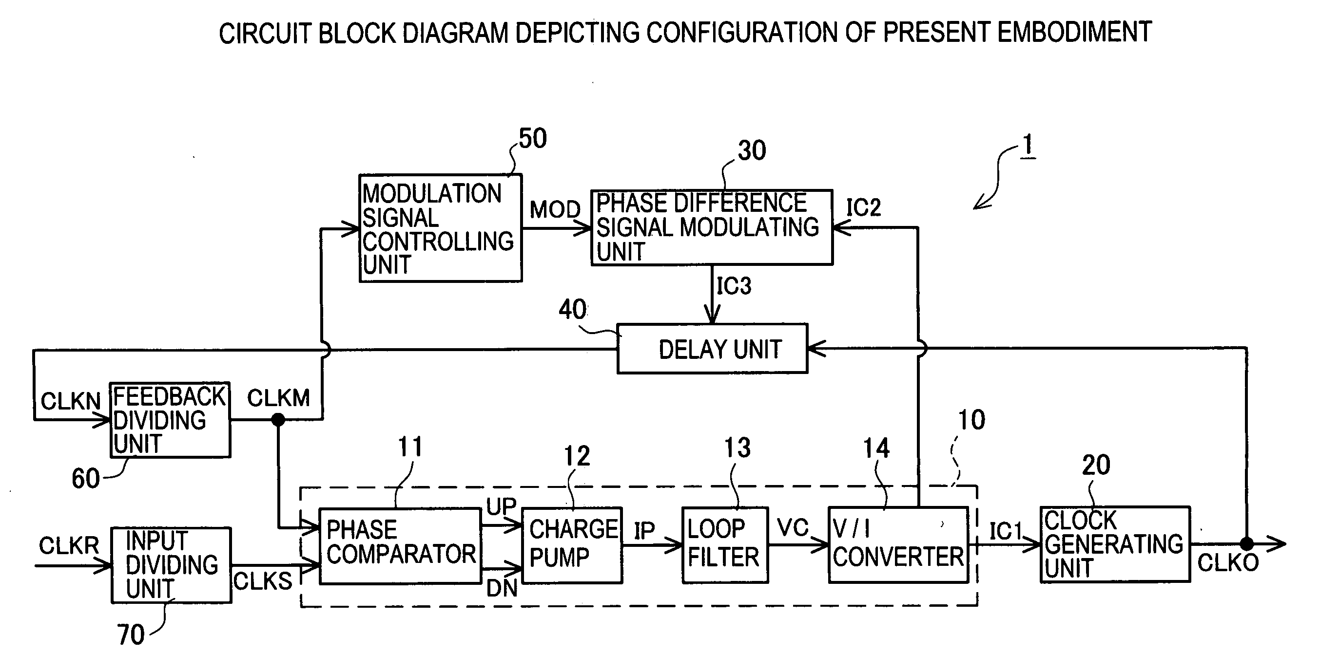
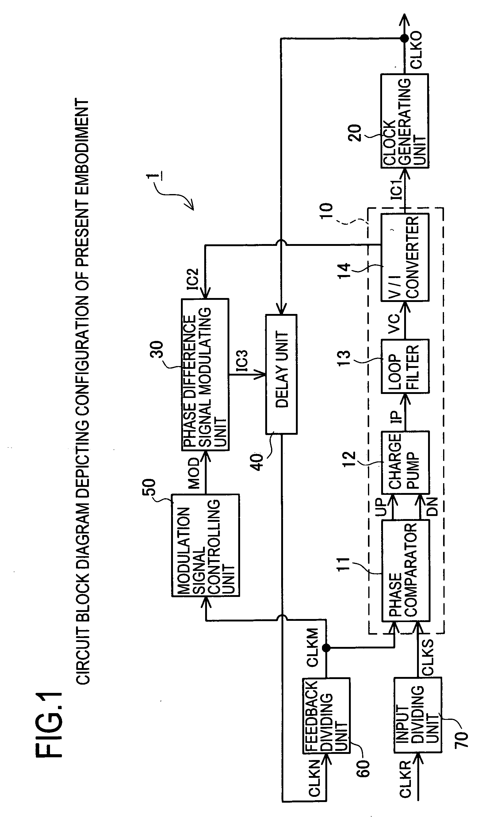
[0030]FIG. 1 is a circuit block diagram depicting an embodiment of a spectrum spread clock generating circuit 1. The spectrum spread clock generating circuit 1 includes a phase comparator unit 10, a clock generating unit 20, a phase difference signal modulating unit 30, a delay unit 40, a modulation signal control unit 50, a feedback dividing unit 60, and an input dividing unit 70. Of these, the feedback dividing unit 60 divides an internal clock signal CLKN into ten sections and outputs a divided internal clock signal CLKM.

[0031] Of these components, the phase comparator unit 10, clock generating unit 20, delay unit 40 and feedback dividing unit 60 compose a PLL (Phase Lock Loop) circuit, and the reference clock signal CLKS and divided internal clock signal CLKM are cont...


PUM


Abstract

The invention provides a clock generating circuit for generating a spectrum spread clock and carrying out high-speed and accurate phase control of a reference clock signal and an output clock signal, which is composed of compact circuits, and a method for generating the clock. The spectrum spread clock generating circuit 1 is provided with a phase comparator unit 10 that compares the reference clock signal CLKS with the internal clock signal in terms of a phase difference, and outputs a control current IC1 in compliance with the result of comparison; a clock generating unit 20 for generating an output clock signal CLKO; a phase difference signal modulating unit 30 for outputting a control current IC3; and a delay unit 40 for delaying the output clock in compliance with the control current IC3 and outputting the internal clock signal CLKN.

Description

CROSS-REFERENCE TO RELATED APPLICATIONS [0001] This application is based upon and claims the benefit of priority from each of the prior Japanese Patent Application No. 2005-183645 filed on Jun. 23, 2005, the entire contents of which are incorporated herein by reference. BACKGROUND OF THE INVENTION [0002] 1. Field of the Invention [0003] The present invention relates to a clock generating circuit, and in particular, to a clock generating circuit for modulating a frequency for spectrum spread by controlling the phase difference between a reference clock and an output clock at high accuracy, and a method for controlling the same. [0004] 2. Description of the Related Art [0005] In recent years, a spectrum spread clock generator (hereinafter also called an “SSCG”) has been spotlighted, which reduces EMI (Electro Magnetic Interference) noise. The SSCG is provided with a PLL circuit and spreads a frequency spectrum of an output clock signal by locking the frequency for the reference clock ...

Claims


Application Information

Patent Timeline
Patent Type & Authority Applications(United States)
IPC IPC(8): H03L7/06H03C3/00H03K5/13H03L7/081H03L7/18
CPCH03L7/081H03K5/13
Inventor YAMAMOTO, SHINICHIOKADA, KOJITANAKA, MASAHIRO
Owner MONTEREY RES LLC
Why Eureka
Try Eureka