Adjustable damping force hydraulic shock absorber

a technology of hydraulic shock absorber and damping force, which is applied in the direction of shock absorbers, mechanical equipment, transportation and packaging, etc., can solve the problems of increasing the number of constituting parts such as orifices, check valves and the like, and the structure of the hydraulic pipe path becomes complicated, and achieves the effect of simplifying the structure of the hydraulic pipe path

Inactive Publication Date: 2007-01-04
SHOWA CORP
View PDF18 Cites 51 Cited by
  • Summary
  • Abstract
  • Description
  • Claims
  • Application Information

AI Technical Summary

Benefits of technology

[0009] An object of the present invention is to simplify a structure of a hydraulic pipe path, in a hydraulic shock absorber in which oil supply and discharge directions in a cylinder are set to different directions in a push pull stroke, and which is provided with a single damping force adjusting valve.

Problems solved by technology

However, in the hydraulic shock absorber of patent document 1, because the damping force adjusting valve is the pilot type, in addition to the structure in which the oil supply and discharge directions in the cylinder are set to the different directions in the push pull stroke, the structure of the hydraulic pipe path becomes complicated, the number of the constituting parts such as an orifice, a check valve and the like is increased, and it is difficult to assemble them.

Method used


Image

  • Adjustable damping force hydraulic shock absorber
  • Adjustable damping force hydraulic shock absorber
  • Adjustable damping force hydraulic shock absorber

Examples


Embodiment Construction

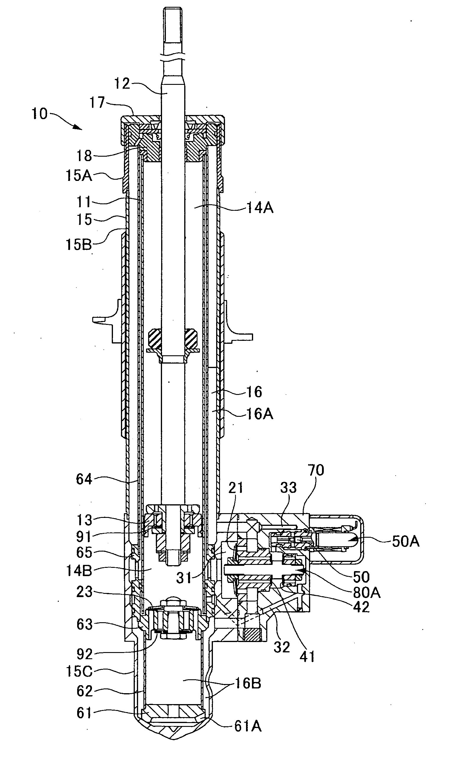
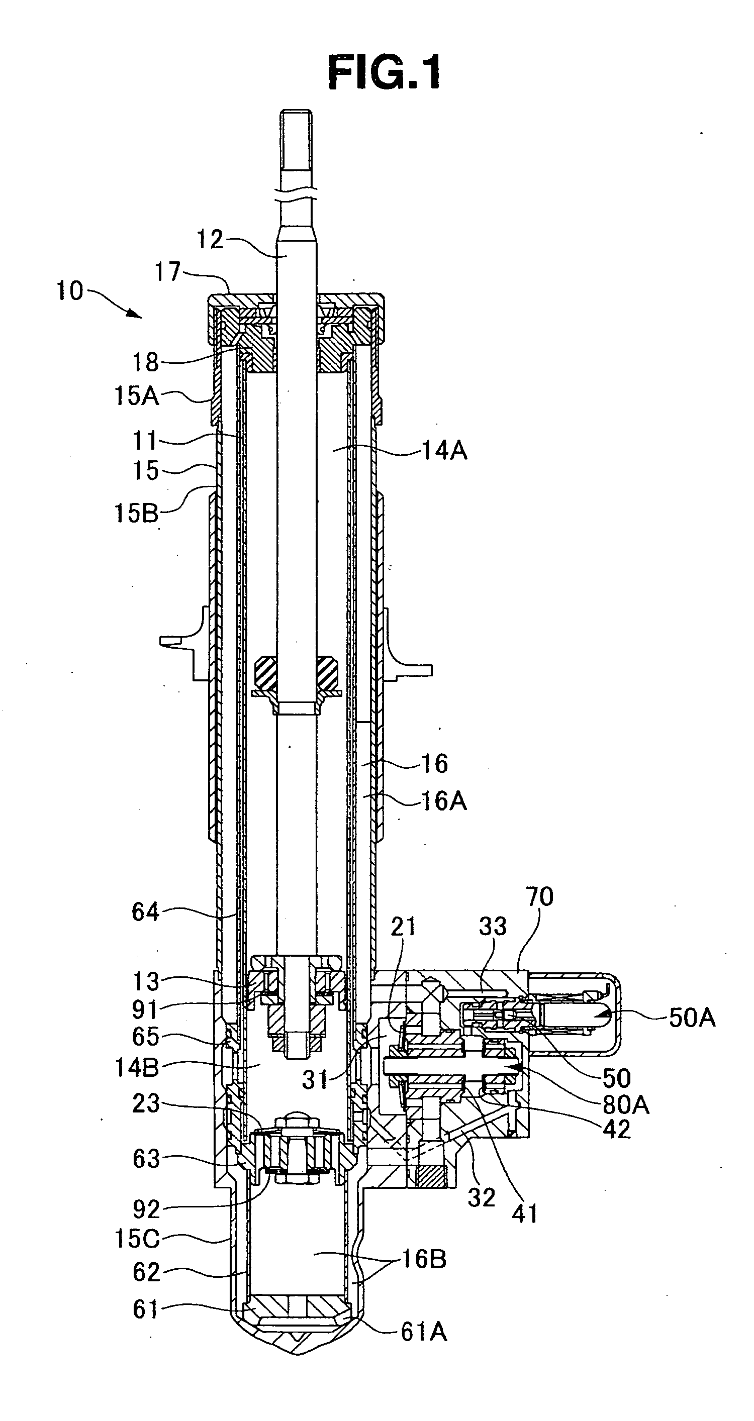
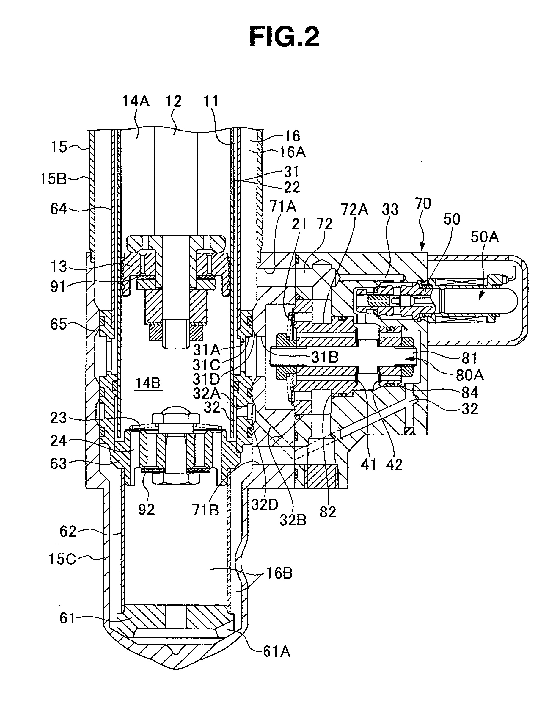
[0018] A hydraulic shock absorber 10 has a cylinder 11 receiving an oil, a piston rod 12 inserted to the cylinder 11, and a piston 13 connected to the piston rod 12 and sectioning a rod side chamber 14A and a piston side chamber 14B in an inner portion of the cylinder 11, as shown in FIG. 1. Further, an outer tube 15 is provided in an outer periphery of the cylinder 11 via an annular gap, and a reservoir 16 sealing an oil and a gas is formed in the outer tube 15.

[0019] The hydraulic shock absorber 10 is structured such that a cap 17 is attached to an upper end portion of the outer tube 15, and a rod guide 18 is pinched between the cap 17 and an upper end portion of the cylinder 11. The rod guide 18 seals the rod side chamber 14A and the reservoir 16, and slidably supports the piston rod 12 while being provided with an oil seal and a dust seal.

[0020] The hydraulic shock absorber 10 has a compression side passage 22 having a compression side check valve 21 allowing only an oil flow ...


PUM


Abstract

A damping force adjustable hydraulic shock absorber is provided with a first passage connected to a rod side chamber, a second passage connected to a piston side chamber, a main passage combining the first passage and the second passage so as to communicate with a reservoir, a first check valve allowing only an oil flow to the main passage from the rod side chamber via the first passage, and a second check valve allowing only an oil flow to the main passage from the piston side chamber via the second passage, and a proportional solenoid type relief valve provided in the main passage, and adjusting a damping force by controlling a relief pressure of the oil flow to the reservoir from the rod side chamber or a relief pressure of the oil flow to the reservoir from the piston side chamber.

Description

BACKGROUND OF THE INVENTION [0001] 1. Field of the Invention [0002] The present invention relates to an adjustable damping force hydraulic shock absorber. [0003] 2. Description of the Related Art [0004] A hydraulic shock absorber used in a suspension apparatus of a motor vehicle or the like has an adjustable damping force which may be adjusted for improved ride quality and steering stability in correspondence to a road surface condition, a traveling condition or the like. [0005] A hydraulic shock absorber in Japanese Patent Application Laid-open No. 9-303471 (patent document 1) has a cylinder receiving an oil, a piston rod inserted to the cylinder, a piston connected to the piston rod and sectioning a rod side chamber and a piston side chamber in an inner portion of the cylinder, and a reservoir sealing the oil and a gas. Further, the hydraulic shock absorber has a first passage connected to the rod side chamber, a second passage connected to the piston side chamber, a main passage ...

Claims


Application Information

Patent Timeline
Patent Type & Authority Applications(United States)
IPC IPC(8): F16F9/54
CPCB60G15/12B60G17/0416F16F9/46F16F9/062F16F9/325B60G17/056
Inventor NAITOU, TUTOMUTANAKA, KATSUSHIMAEDA, KAZUNARI
Owner SHOWA CORP
Why Eureka
Try Eureka