Active bandwidth control for a laser

Active Publication Date: 2007-01-04
CYMER INC
View PDF77 Cites 50 Cited by
  • Summary
  • Abstract
  • Description
  • Claims
  • Application Information

AI Technical Summary

Benefits of technology

[0011] In a first aspect of an embodiment of the present invention, a lithography apparatus for exposing a resist with a pre-selected pattern may comprise a mask designed using optical proximity correction (OPC) to produce the pre-selected pattern on the resist. For this aspect, the apparatus may include a laser source for generating a laser light beam for transmission through the mask to expose the resist and an instrument measuring laser bandwidth. In addition, the laser source may comprise an active bandwidth control system to increase a bandwidth of a subsequent pulse in response to a measured pulse bandwidth that is below a predetermined bandwidth range and decrease a bandwidth of a subsequent pulse in response to a measured pulse bandwidth that is above the predetermined bandwidth range.
[0012] In another aspect of an embodiment of the present invention, an active bandwidth control system operable within a burst of pulses

Problems solved by technology

In short, large bandwidths have been troublesome because, as indicated above, lithography tool optics are generally designed for a specific center

Method used


Image

  • Active bandwidth control for a laser
  • Active bandwidth control for a laser
  • Active bandwidth control for a laser

Examples


Embodiment Construction

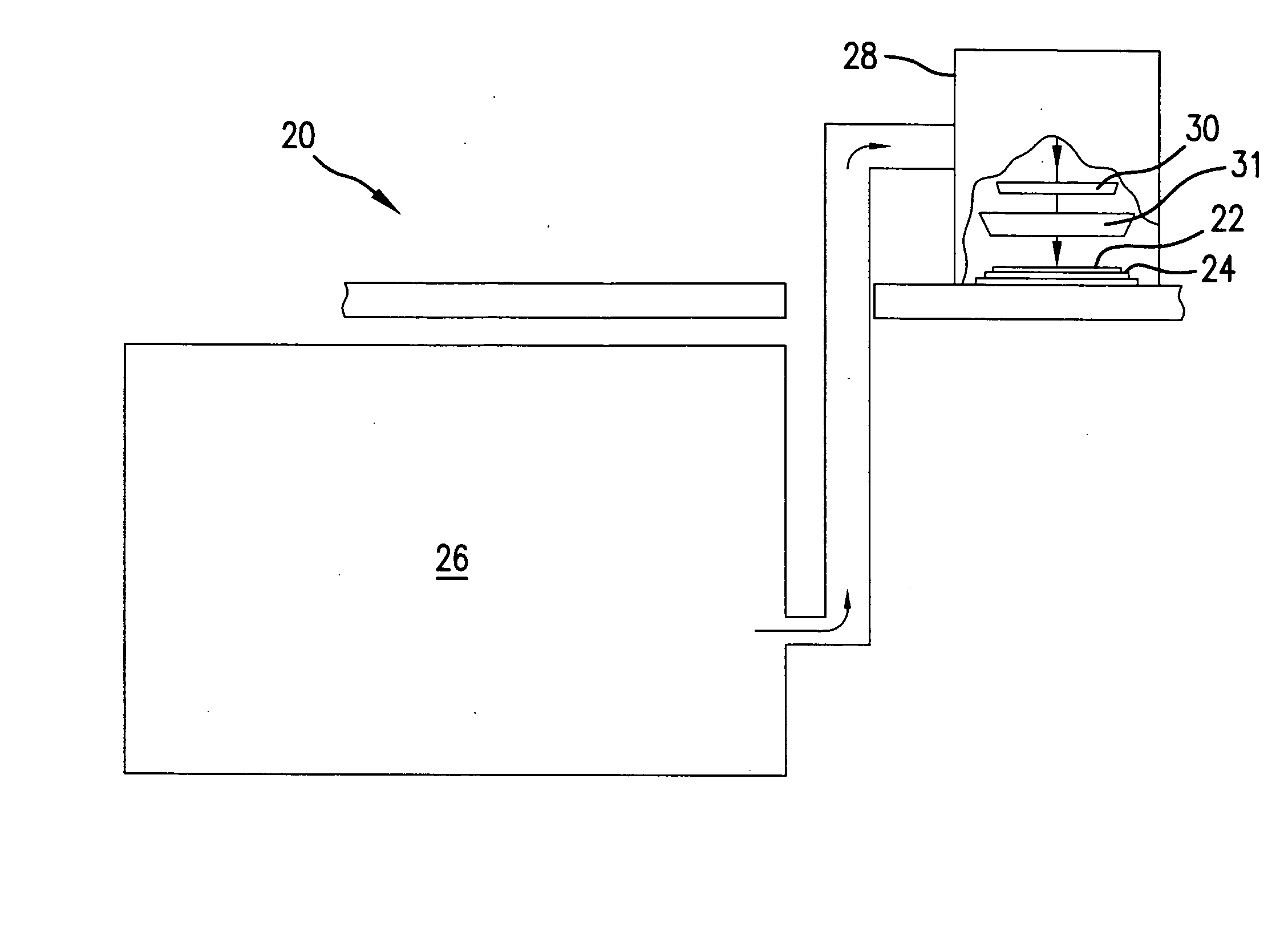
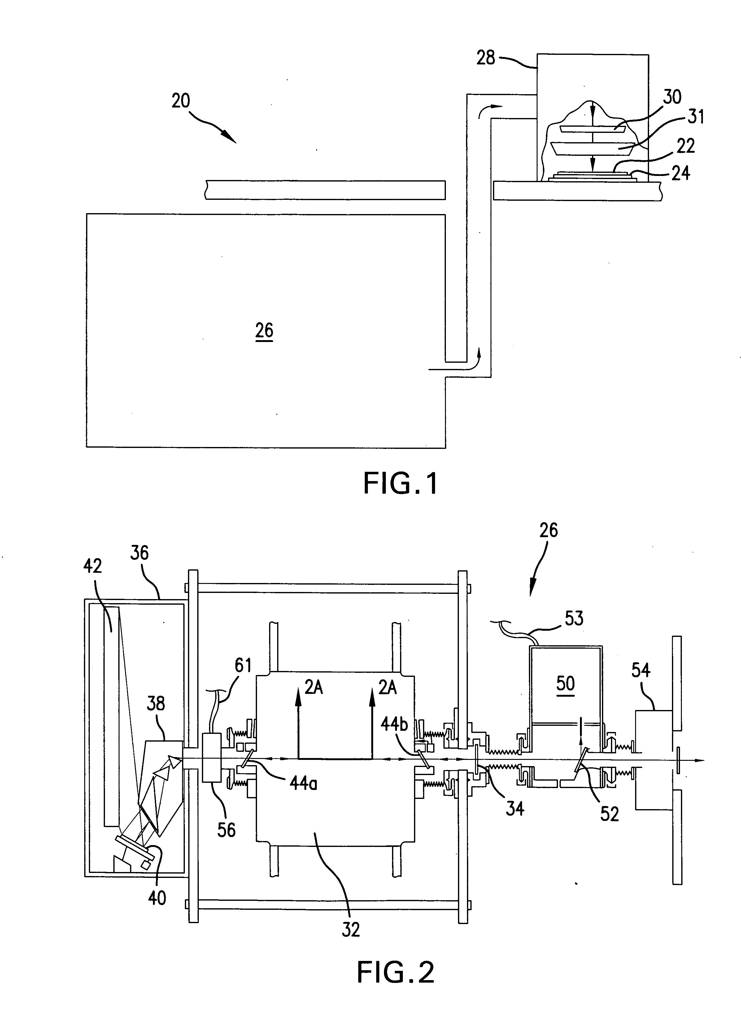
[0024] With initial reference to FIG. 1, a lithography apparatus is shown and generally designated 20 which can be used, for example, to expose a selected pattern on a photoresist layer 22 that has been deposited on a wafer 24. As shown, the primary components of the apparatus 20 include a laser source 26 and a lithography tool 28, which may be a scanner, stepper, step and scan or any other suitable lithography tool known in the pertinent art. For the apparatus 20, the laser source 26 may be a line-tuned gas discharge laser, e.g., a pulsed KrF excimer lasers, pulsed ArF excimer laser or pulsed molecular fluorine (F2) laser having a line narrowing module, and may include one or more discharge chambers. In particular, the laser source 26 may include one or more oscillator chambers, so-called power oscillators (if laser seeded) and master oscillators (if unseeded), and may include one or more laser seeded amplifying chambers, so-called power amplifiers. Alternatively, as shown in FIG. ...


PUM


Abstract

In a first aspect, a lithography apparatus may comprise a mask designed using optical proximity correction (OPC), a pulsed laser source, and an active bandwidth control system configured to increase the bandwidth of a subsequent pulse in response to a measured pulse bandwidth that is below a predetermined bandwidth range and increase a bandwidth of a subsequent pulse in response to a measured pulse bandwidth that is above the predetermined bandwidth range. In another aspect an active bandwidth control system may include an optic for altering a wavefront of a laser beam in a laser cavity of the laser source to selectively adjust an output laser bandwidth in response to the control signal. In yet another aspect, the bandwidth of a laser having a wavelength variation across an aperture may be actively controlled by an aperture blocking element that is moveable to adjust a size of the aperture.

Description

FIELD OF THE INVENTION [0001] The present invention relates to lasers. The present invention is particularly, but not exclusively useful for providing a laser output having a bandwidth that is controlled within a pre-selected range. BACKGROUND OF THE INVENTION [0002] Pulsed lasers, such as KrF excimer lasers, ArF excimer lasers and molecular fluorine (F2) lasers, are often used in conjunction with a lithography tool to selectively expose a photoresist in a semiconductor wafer fabrication process. In these processes, the mask and optics in the lithography tool are typically optimized for a particular laser wavelength. More specifically, the tool is typically optimized for a particular center wavelength. For a variety of reasons, the center wavelength of the light exiting the laser may drift over time and, thus, a feedback network may be employed to detect the center wavelength exiting the laser and modify one or more laser parameters to correct the wavelength as necessary. [0003] Rec...

Claims


Application Information

Patent Timeline
IPC IPC(8): A61N5/00
CPCG03F7/70025G03F7/70575H01S3/005H01S3/225H01S3/106H01S3/137H01S3/08036
Inventor REILEY, DANIEL J.RYLOV, GERMAN E.BERGSTEDT, ROBERT A.
Owner CYMER INC
Why Eureka
Try Eureka