Magnetic core member, antenna module, and mobile communication terminal having the same

Inactive Publication Date: 2007-01-04
SONY CORP
View PDF4 Cites 62 Cited by
  • Summary
  • Abstract
  • Description
  • Claims
  • Application Information

AI Technical Summary

Benefits of technology

[0020] Even alternatively, if machined marks are formed in the first surface of the magnetic core member, magnetic paths in the first surface are split by the machined marks, to suppress eddy currents occurring in the first surface. This permits enhancement of the communication distance of the antenna coil. Likewise, by providing the first surface with irregularities, similar advantages can be obtained.
[0021] As mentioned above, according to the magnetic core member of the present invention, it becomes possible to satisfy enhancement of the communication distance of the antenna coil, as well as a sufficient electromagne

Problems solved by technology

However, since the antenna module having the above-mentioned configuration has its magnetic core member made of an amorphous sheet or an electromagnetic steel strip, a Q factor usable for frequencies of about 100 kHz is obtainable, but for a case of a high frequency such as several MHz to several tens of MHz, there has been an inconvenience that its Q factor drops due to eddy currents occurring in the amorphous sheet or the electromagnetic steel strip of the magnetic core member.
Particularly, in recent years, IC tags using the RFID technology operating at 13.56 MHz have come into practice, and the antenna module disclosed in Japanese Patent Application Publication No. 2000-48152 is not usable for tags operating in such high-frequency electric waves.
However, the sintered ferrite is comparatively fragile.
Particularly, when a sintered ferrite plate is made thin for use as a magnetic core member

Method used


Image

  • Magnetic core member, antenna module, and mobile communication terminal having the same
  • Magnetic core member, antenna module, and mobile communication terminal having the same
  • Magnetic core member, antenna module, and mobile communication terminal having the same

Examples


Example

FIRST EMBODIMENT

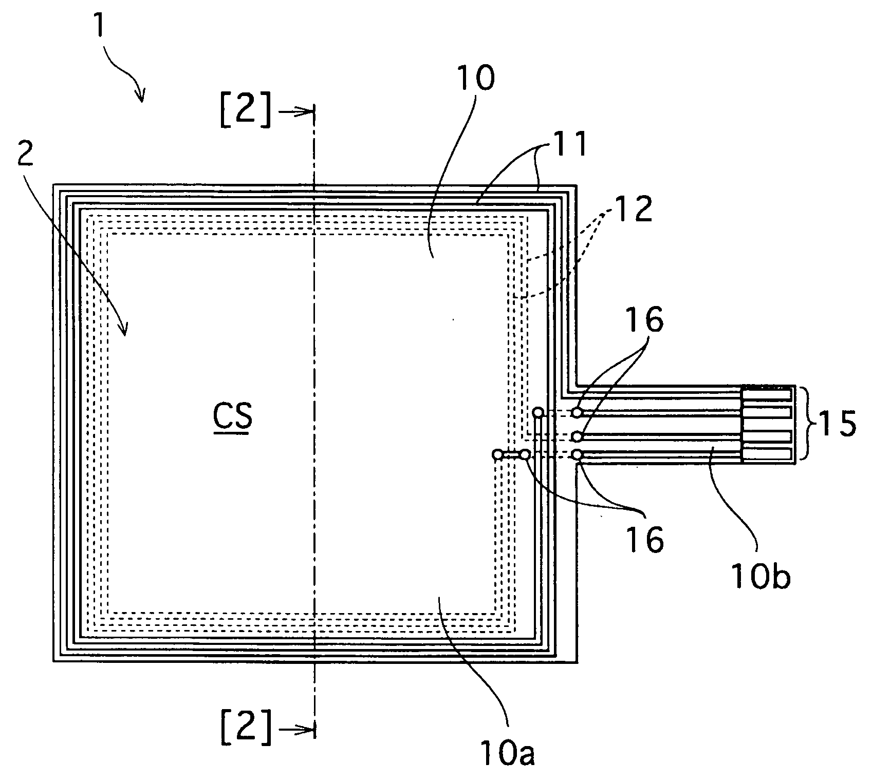
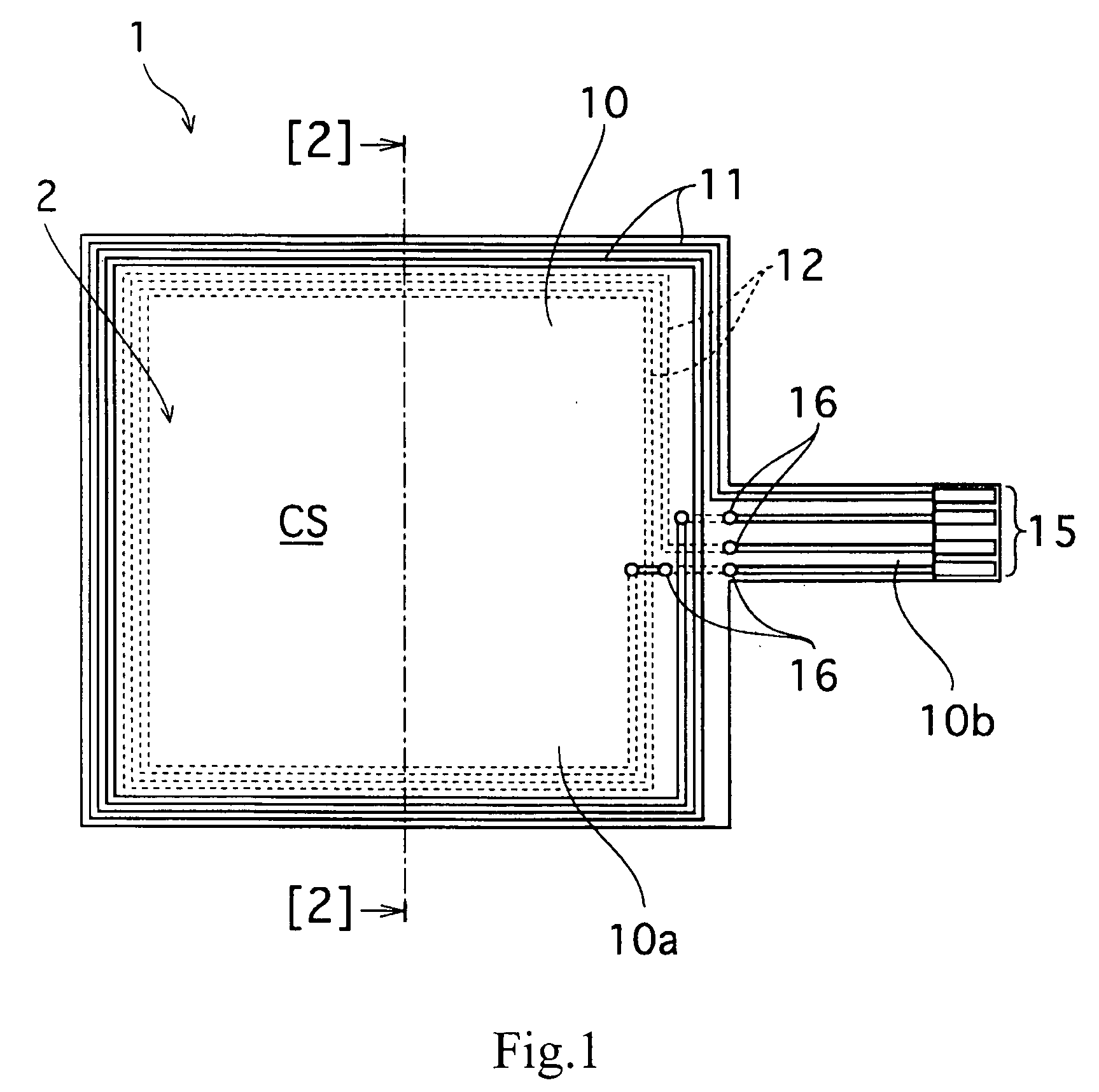
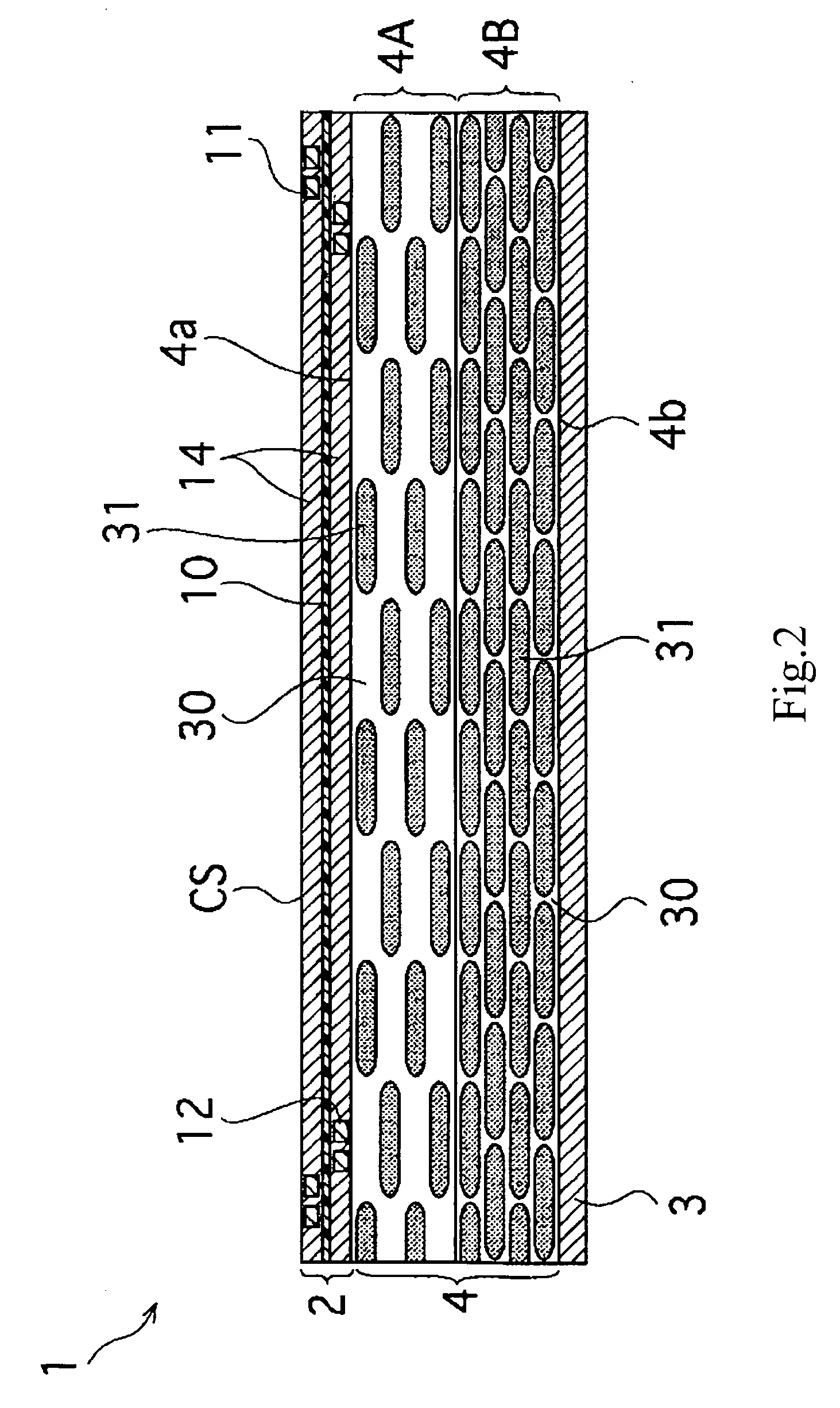
[0038]FIGS. 1 and 2 show the configuration of an antenna module 1 according to a first embodiment of the present invention. Here, FIG. 1 is a plan view of the antenna module 1, and FIG. 2 is a sectional view taken along a line [2]-[2] in FIG. 1.

[0039] The antenna module 1 includes an antenna substrate 2 having first and second antenna coils 11, 12 formed therein, a shield plate 3, and a magnetic core member 4 disposed between the antenna substrate 2 and the shield plate 3.

[0040] In the antenna substrate 2, the first antenna coil 11 for communication with a reader / writer, and the second antenna coil 12 for communication with an IC tag, such as an IC card, are disposed and formed on a common base film 10. The first antenna coil 11 is disposed and formed on a surface side (communication surface CS) of the base film 10, and the second antenna coil 12 is disposed and formed on an rear-surface side (a side opposite to the communication surface CS) of the base film 10 (F...

Example

SECOND EMBODIMENT

[0073] Referring next to FIG. 6, the configuration of an antenna module in a second embodiment of the present invention will be described. Note that in the figure, portions corresponding to those of the first embodiment are denoted by the same reference symbols, and that their detailed descriptions are omitted.

[0074] A magnetic core member 42 forming an antenna module 1 according to the present embodiment has a two-layered structure including a first layer 42A on the side of an antenna substrate 2 and a second layer 42B on the side of a shield plate 3.

[0075] Each of the first layer 42A and the second layer 42B of the magnetic core member 42 is formed by filling an insulating material (binder) 30, such as a synthetic resin, with a soft magnetic powder 31. The soft magnetic powder 31 is aligned parallel to the sheet surface.

[0076] In the present embodiment, similarly to the above-mentioned first embodiment, the filling rate of the soft magnetic powder 31 is made t...

Example

THIRD EMBODIMENT

[0086]FIG. 7 shows the configuration of an antenna module in a third embodiment of the present invention. It is noted that in the figure, portions corresponding to those of the above-mentioned first embodiment are denoted by the same reference symbols, and that their detailed descriptions are omitted.

[0087] A magnetic core member 43 forming an antenna module 1 according to the present embodiment has a two-layered structure including a first layer 43A on the side of an antenna substrate2 and a second layer 43B on the side of a shield plate 3. Each of the first layer 43A and the second layer 43B of the magnetic core member 43 is formed by filling an insulating material (binder) 30, such as a synthetic resin, with a soft magnetic powder 31.

[0088] In the present embodiment, the soft magnetic powders 31 in a first surface 43a opposed to the antenna substrate 2 and a second surface 43b opposed to the shield plate 3, of the magnetic core member 43, are aligned differentl...


PUM


Abstract

A magnetic core member, an antenna module, and a portable communication terminal having this, which have a configuration capable of satisfying enhancement of communication characteristics of antenna coils as well as their sufficient electromagnetic shielding function from a shield plate. A magnetic core member (4) is disposed between an antenna substrate having antenna coils (11), (12) formed therein and a conductive shield plate (3), and is formed by filling an insulating material (30) with a magnetic powder (31). The magnetic core member (4) has a two-layered structure including a first layer (4A) and a second layer (4B), thereby making a filling rate of the magnetic powder (31) in the first layer (4A) be lower than that of the magnetic powder (31) in the second layer (4B) so that a first surface (4a) on a side opposed to the antenna substrate (2) and a second surface (4b) on a side opposed to the shield plate (3) have magnetic properties different from each other.

Description

TECHNICAL FIELD [0001] The present invention relates to a magnetic core member, an antenna module, and a portable communication terminal having this, adapted for use in IC tags using RFID (Radio Frequency Identification) technology. BACKGROUND ART [0002] Conventionally, as an IC card and an identification tag using RFID technology (these are hereinafter referred to collectively as “IC tag” as well), devices are known in which an IC chip having recorded information therein and a resonant capacitor are electrically connected to an antenna coil. In these devices, it is configured to implement identification or monitoring by transmitting an electric wave of a predetermined frequency from a transmission / reception antenna of a reader / writer to the antenna coil, to activate an IC tag, and then to read the information stored in the IC chip in accordance with a read command based on data communication via the electric wave, or depending on whether or not resonance occurs with the electric wa...

Claims


Application Information

Patent Timeline
IPC IPC(8): H01Q7/08G06K17/00G06K19/07G06K19/077H01Q1/24H01Q1/38H01Q1/52H01Q7/06H01Q17/00H01Q19/10H04B1/59
CPCH01Q1/38H01Q19/10H01Q7/06H01Q7/00
Inventor TAKAHASHI, ISAONOZAWA, KAZUOAKIHO, HIRAKU
Owner SONY CORP
Why Eureka
Try Eureka