Droplet ejection apparatus

a technology of ejection apparatus and droplet, which is applied in the direction of photomechanical apparatus, instruments, printing, etc., can solve the problems of time and effort, difficult to accurately control parameters concerning difficult to accurately control parameters of droplet discharge and laser irradiation, etc., to achieve accurate and fast alignment of ejection droplets and easy control

Inactive Publication Date: 2007-01-04
SEIKO EPSON CORP
View PDF6 Cites 4 Cited by
  • Summary
  • Abstract
  • Description
  • Claims
  • Application Information

AI Technical Summary

Benefits of technology

[0007] An advantage of the invention is to provide a droplet ejection apparatus that enables easy control of parameters concerning droplet ejection and laser irradiation and that enables accurate and speedy alignment of the ejected droplet with the laser spot.
[0008] According to the present invention, a droplet ejection apparatus includes: a base; a plotting system having a droplet ejection head that ejects functional liquid as a droplet, a carriage that holds the droplet ejection head, and a stage that holds a work at which the droplet is plotted; and an optical system having a light source that outputs a laser beam and an optical path, which is constituted between the light source and the droplet and through which the laser beam passes to irradiate the droplet; wherein: the plotting system and the optical system are established on the base sharing the upper surface of the base as a reference surface, and pattern is plotted and fixed through cooperation control of both systems.
[0009] With the droplet ejection apparatus, it is preferable that the optical path includes a first optical path through which the laser beam is irradiated on the droplet from an upper direction against the stage.
[0010] With the droplet ejection apparatus, it is preferable that the optical path includes a second optical path through which the laser beam is irradiated on the droplet diagonally against the stage.
[0011] With the droplet ejection apparatus, it is preferable that the optical path includes a second optical path through which the laser beam is irradiated on the droplet horizontally against the stage.
[0012] It is preferable that the droplet ejection apparatus further includes a protection cover that protects the droplet ejection head from the laser beam, the side surface of the protection cover being usable as a plane surface for verification of a laser spot position when adjusting the path of the third optical path.

Problems solved by technology

However, because it takes long time for the process, there are the cost and energy problems.
In the device shown in JP-A-2004-241770, it is difficult to accurately control parameters concerning droplet discharge and laser irradiation, such as the time needed between the landing of the droplet on the work and the laser irradiation because the plotting system that discharges the conductive material and the optical system that irradiates the discharged conductive material with the lamp or laser light are provided separately from each other.
Further, because the device of JP-A-2004-241770 has the plotting system and the optical system on different reference surfaces, it takes time and effort to align the plotted conductive layer with the laser light irradiation spot.
Moreover, because the work is transported from the inkjet process chamber to the laser irradiation chamber, it requires time for the transportation.

Method used


Image

  • Droplet ejection apparatus
  • Droplet ejection apparatus
  • Droplet ejection apparatus

Examples


Embodiment Construction

[0039] In an exemplary embodiment of the invention, the base is a vibration-proof base, and the plotting system and the optical system are established on the upper surface of the vibration-proof base as the reference surface. The plotting system and the optical system can be mounted on the base by such well-known anchoring means as bolts and nuts, chucks, welding, and bonding.

[0040] One working example of the invention will now be described referring to the drawings.

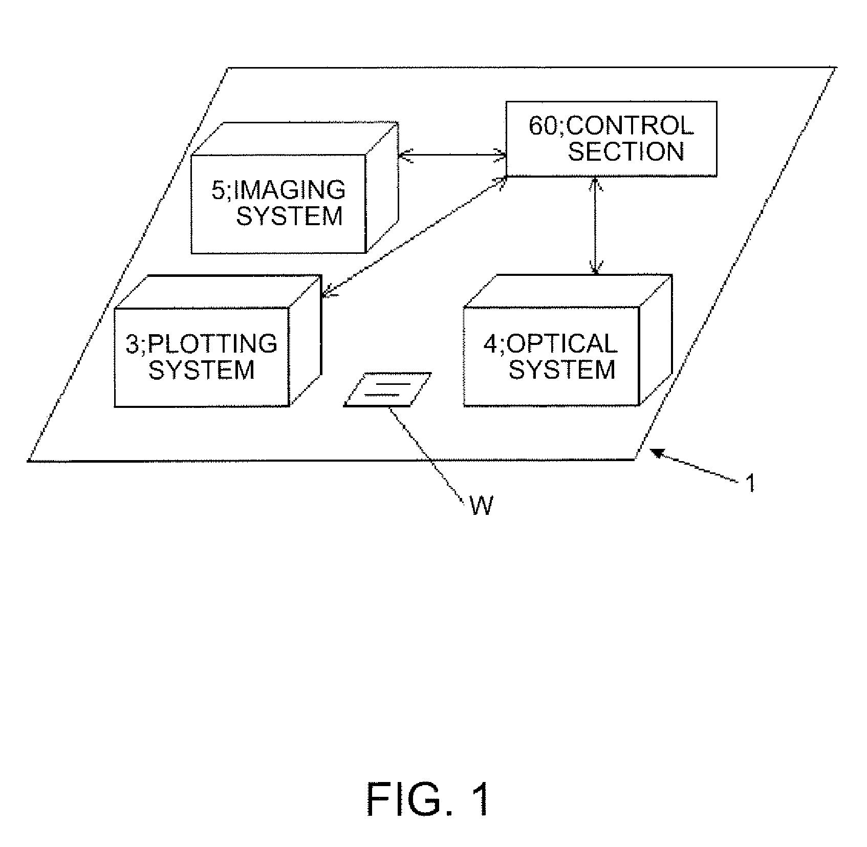
[0041]FIG. 1 is a schematic block diagram to explain the control structure of a droplet ejection apparatus according to one working example of the invention.

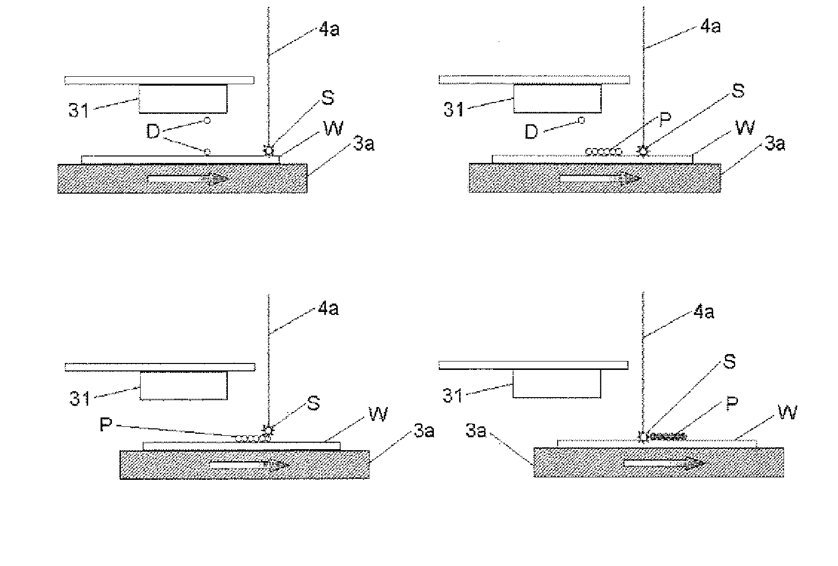
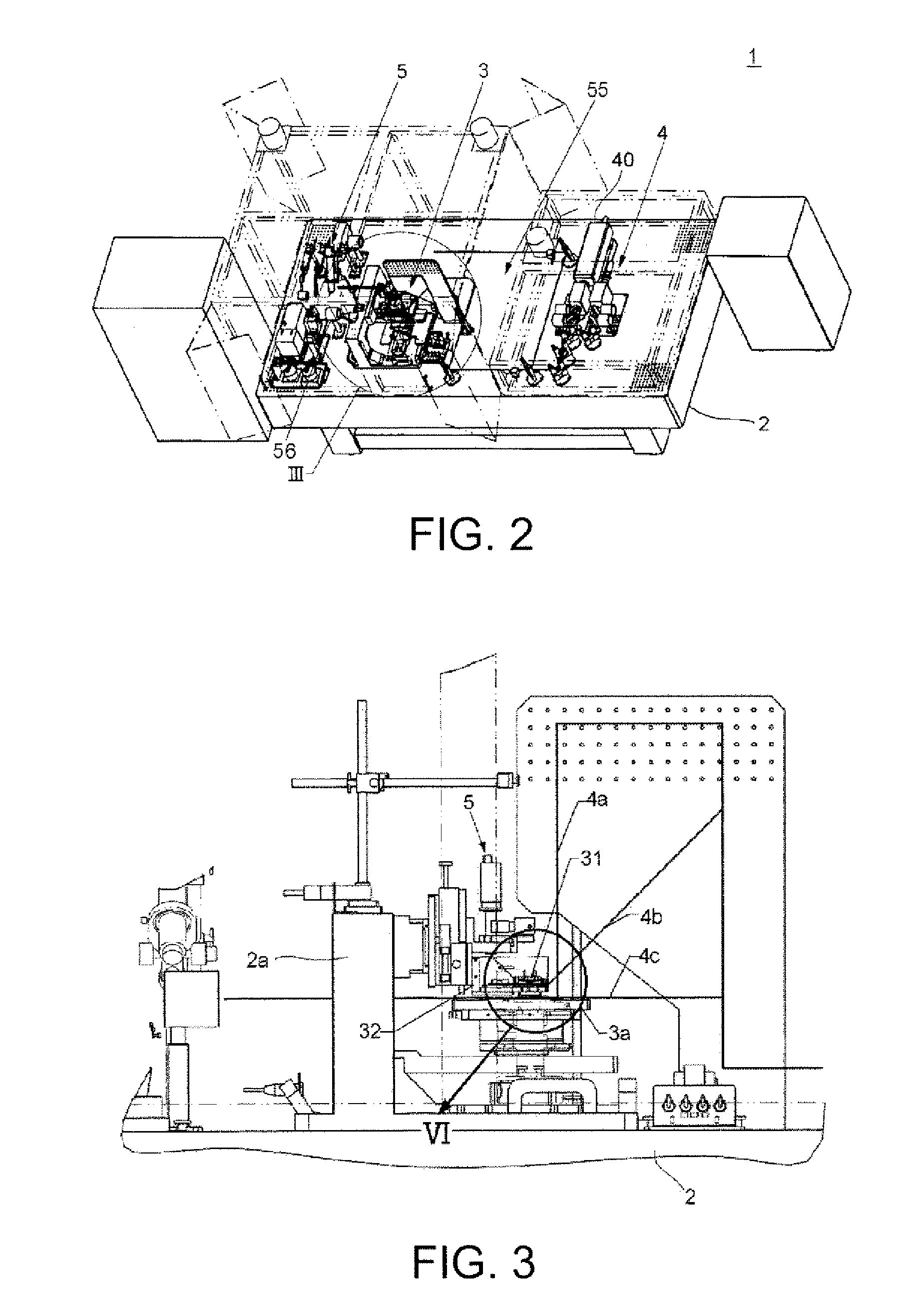
[0042]FIG. 1 illustrates the basic control structure of the droplet ejection apparatus according to one working example of the invention, which includes: on a base 1 whose upper surface being shared as the reference surface, a plotting system 3 that contains a droplet ejection head 31 and the like (see FIG. 2); an optical system 4 that contains first to third opti...


PUM


Abstract

A droplet ejection apparatus includes: a base; a plotting system having a droplet ejection head that ejects functional liquid as a droplet, a carriage that holds the droplet ejection head, and a stage that holds a work at which the droplet is plotted; and an optical system having a light source that outputs a laser beam and an optical path, which is constituted between the light source and the droplet and through which the laser beam passes to irradiate the droplet; wherein: the plotting system and the optical system are established on the base sharing the upper surface of the base as a reference surface, and pattern is plotted and fixed through cooperation control of both systems.

Description

BACKGROUND [0001] 1. Technical Field [0002] The present invention relates to a droplet ejection apparatus, particularly to a droplet ejection apparatus having a plotting system that ejects droplets and an optical system that irradiates the ejected droplets with laser beams, and more particularly to a droplet ejection apparatus that forms wiring patterns. [0003] 2. Related Art [0004] When patterning metal wiring using a droplet ejection technique, it needs to reduce process time, cost, and energy in the drying and baking process. At present, the drying and baking is conducted using a hot plate or a clean oven. However, because it takes long time for the process, there are the cost and energy problems. Thus, a process is proposed by which a metal wiring pattern is formed by discharging droplets, and, thereafter, the drying and baking is conducted using laser. [0005] JP-A-2004-241770 proposes an inkjet device, with which a conductive material is discharged on a work on a substrate to p...

Claims


Application Information

Patent Timeline
Patent Type & Authority Applications(United States)
IPC IPC(8): B41J2/01
CPCB41J11/002H01L21/288H01L21/76838H05K2203/107H05K3/125H05K3/1283H01L51/0022H10K71/611G03F7/0002G03F7/2018H05K3/1291B41J11/0021
Inventor SANEKATA, TAKAHITO
Owner SEIKO EPSON CORP
Why Eureka
Try Eureka