Diffractive lens and scanning lens formed with diffractive lens

a diffractive lens and scanning lens technology, applied in the field of scanning lenses, can solve the problems of deterioration of printed images, affecting the accuracy of scanning images, so as to achieve the effect of high value and retained diffractive efficiency

Inactive Publication Date: 2007-01-04
HOYA CORP
View PDF11 Cites 20 Cited by
  • Summary
  • Abstract
  • Description
  • Claims
  • Application Information

AI Technical Summary

Benefits of technology

[0005] In consideration of the foregoing problems of conventional arts, the present invention is advantageous in that there is provided an improved scanning optical system and a diffractive lens therefor, which is configured such that the stepped portions are hardly distorted when a lens element provided with the diffractive lens structure is formed is made by injection molding so that the diffractive efficiency can be retained at a high value.

Problems solved by technology

When a plurality of light sources are used, however, if the wavelengths of the laser, beams emitted by the plurality of light sources are different from each other, due to longitudinal chromatic aberration provided by the optical system, a scanning width error occurs.
However, if the scanning lens element formed with the diffractive lens structure as disclosed in the '820 publication or '145 publication by the plastic injection molding, when the lens itself contracts when demolded from the molding, stepped surfaces between adjacent annular zones and portions therearound may be distorted.
When such a lens is used, the intensity of light at a peripheral portion is lowered, which results in deterioration of printed images.

Method used


Image

  • Diffractive lens and scanning lens formed with diffractive lens
  • Diffractive lens and scanning lens formed with diffractive lens
  • Diffractive lens and scanning lens formed with diffractive lens

Examples


first embodiment

[0027] First Embodiment

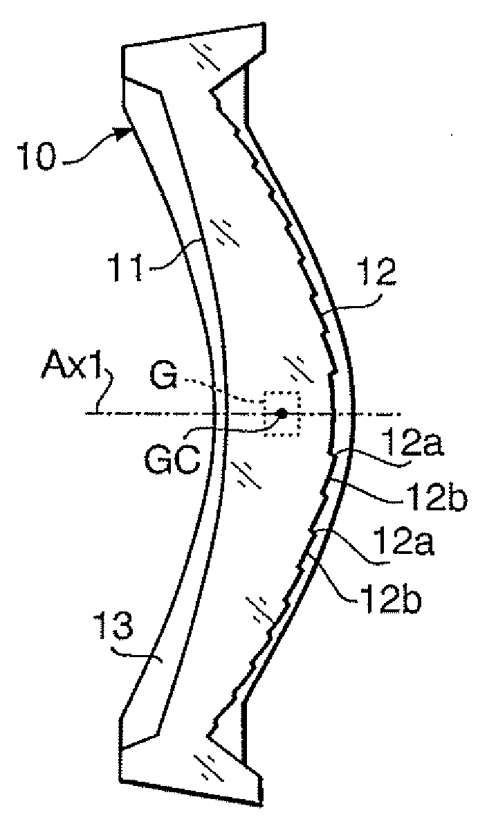
[0028]FIG. 1A shows a cross sectional side view of a scanning lens 10 according to a first embodiment of the invention, and FIG. 1B is a front view of the scanning lens 10 shown in FIG. 1A. It should be noted that FIG. 1A is a view take along line P-P of FIG. 1B. The scanning lens 10 is arranged between a polygonal mirror and a photoconductive drum of a scanning optical system. Specifically, the scanning lens 10 is arranged such that a first surface 11, which is on the left-hand side in FIG. 1A, is on the polygonal mirror side, and a second surface 12, which is on the right-hand side in FIG. 1A, is on the photoconductive drum side. As shown in FIG. 1B around the lens surfaces allowing the light to transmit, a rib 13 used for fixing the scanning lens 10 onto a device is formed. In FIGS. 1A and 1B, G denotes a gate and GC represents the center of the gate.

[0029] Generally, a scanning lens to be used in a laser printer or the like, light scans in one direction (...

second embodiment

[0045] Second Embodiment

[0046]FIG. 9 shows a cross-sectional side view of a scanning lens 100 according to a second embodiment. The scanning lens 100 is particularly effective when a gate is formed on the rib 13 at a position on the optical axis projected on a plane parallel with the main scanning plane.

[0047] The scanning lens 100 is configured such that the first surface 101 is a concave surface, a macroscopic shape of the second surface 102 is a convex surface (i.e., the scanning lens 100 is a positive meniscus lens macroscopically), and a diffractive lens structure is formed on the second surface 102. The diffractive lens structure includes a plurality of rotationally symmetrical annular zones which are concentric about the optical axis Ax1 of the scanning lens 100. The diffractive lens structure includes diffraction operating surfaces 102b that diffract light passing therethrough and stepped surfaces 102a connecting the adjoining diffraction operating surfaces 102b. Around the...


PUM


Abstract

A scanning lens for an imaging optical system converges a beam emitted by a light source and deflected by a deflector on a target surface to form a beam spot scanning in a main scanning direction thereon. The scanning lens includes a plastic lens formed by injection molding, which has a diffractive lens structure on at least one surface thereof. The diffractive Wens structure has a plurality of annular zones arranged concentrically about a rotational axis. Each annular zone has a diffracting surface that diffracts the light beam passing therethrough. The diffractive lens structure has stepped surfaces each connecting adjoining diffracting surfaces In a plane including the rotational axis and parallel with the main scanning direction, the stepped surfaces are inclined with respect to the rotational axis so that stress working between a metallic molding for the plastic lens and each of the stepped surfaces in demolding is reduced.

Description

BACKGROUND OF THE INVENTION [0001] The present invention relates to a scanning lens having a lens element formed with a diffractive lens having a plurality of annular zones on a surface of the lens element, and the diffractive lens formed on the lens element. [0002] Conventionally, a diffractive lens having a lens element formed with a diffiactive lens structure thereon has been widely used for various purposes. Examples of the diffractive lenses are disclosed in Japanese Patent Provisional Publications No. HEI 10-197820 (hereinafter, referred to as '820 publication) and No. HEI 11-095145 (hereinafter, referred to as '145 publication). In each of '820 publication and '145 publication, a scanning optical system including a diffractive lens as a scanning lens is disclosed. The scanning optical system is configured such that, a beam emitted by a laser source is deflected by a deflector such as a polygonal mirror or a galvano mirror to scan within a predetermined angular range. The scan...

Claims


Application Information

Patent Timeline
Patent Type & Authority Applications(United States)
IPC IPC(8): G02B5/18
CPCG02B3/08G02B26/125G02B5/1814
Inventor TAKEUCHI, SHUICHITAKAKUBO, YUTAKA
Owner HOYA CORP
Why Eureka
Try Eureka