Wind noise reduction for microphone

Inactive Publication Date: 2007-01-04
SONY ERICSSON MOBILE COMM AB
View PDF11 Cites 14 Cited by
  • Summary
  • Abstract
  • Description
  • Claims
  • Application Information

AI Technical Summary

Benefits of technology

[0005] The present invention is thus directed towards providing a microphone unit, in particular a directional microphone unit, for

Problems solved by technology

However, although these microphones are considered to be less sensitive to wind-noise from air blowing into the microphone compared to so-called “directional microphones”, wind-noise is often still a problem.
However, a drawback is that due to power consumption, noise cancelling algorithms are not always suitable in portable electronic devices having limited battery capacity.
Moreove

Method used


Image

  • Wind noise reduction for microphone
  • Wind noise reduction for microphone
  • Wind noise reduction for microphone

Examples


Example

[0024] The present invention can be advantageously applied to all types of microphones to reduce sensitivity to wind-noise. Wind-noise is a significant problem particularly in directional microphones, which are more sensitive to this disturbance. Accordingly, the invention will be described with reference to a preferred embodiment in which an electret condenser type directional microphone is used, but is not in any sense limited thereto.

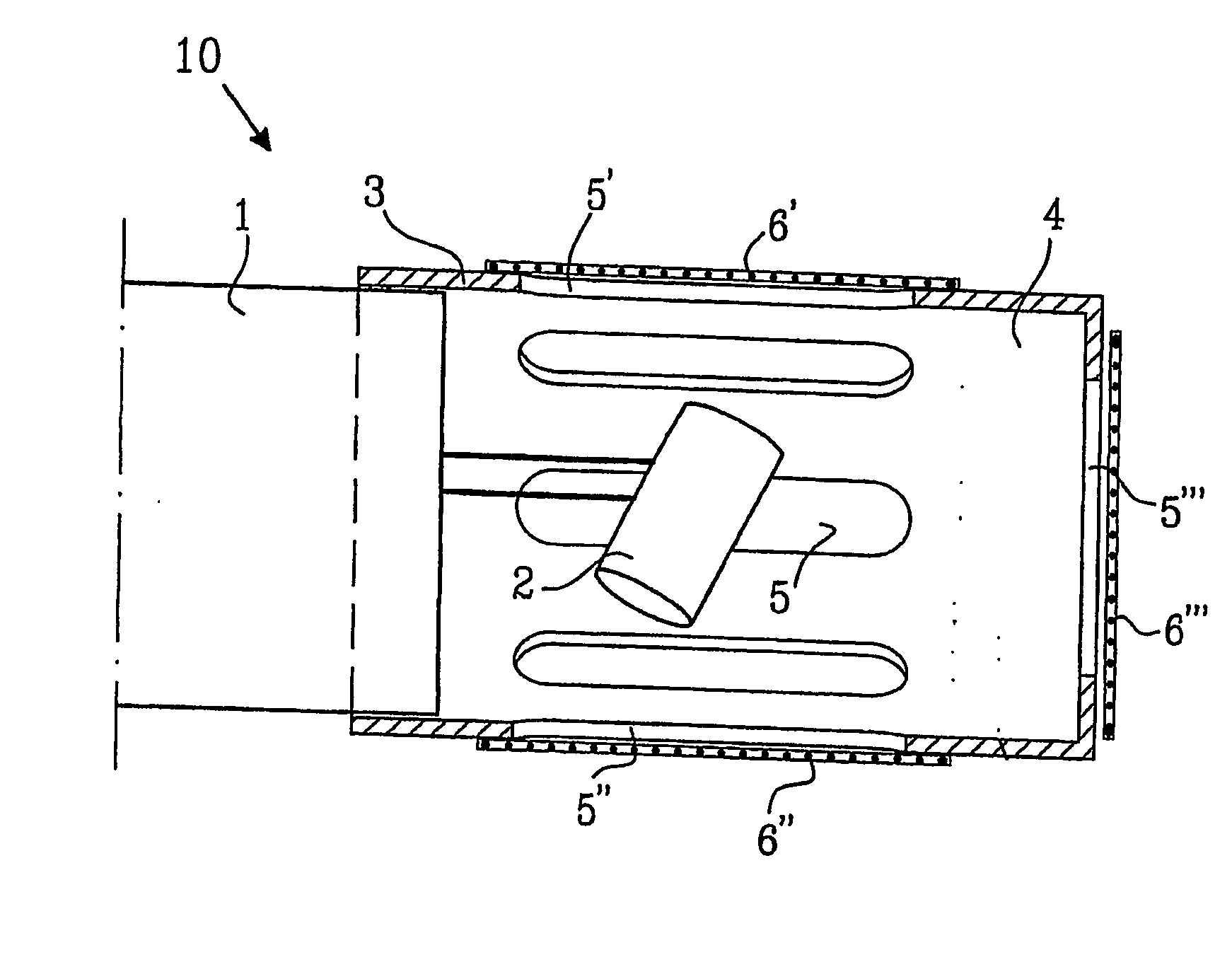
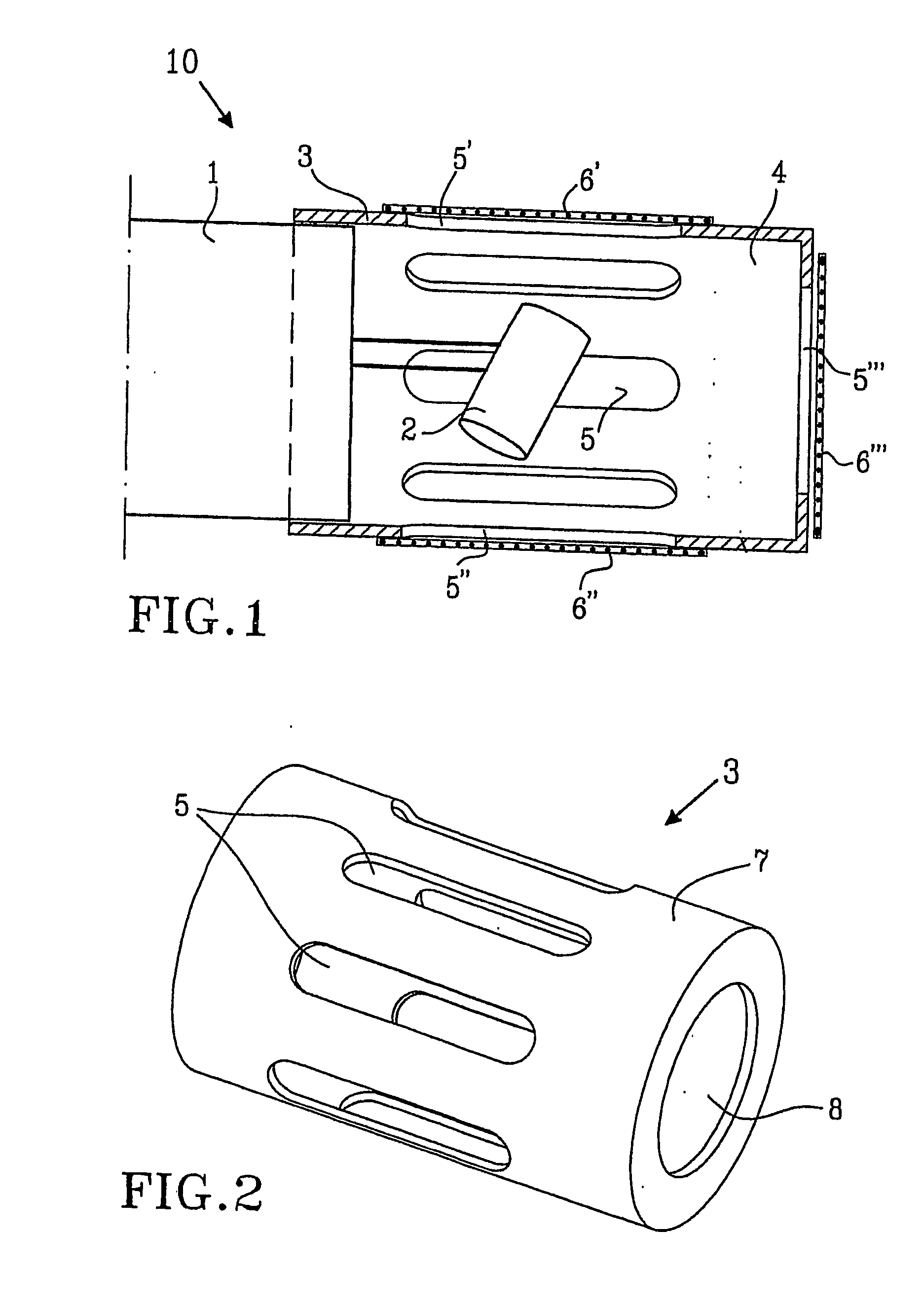
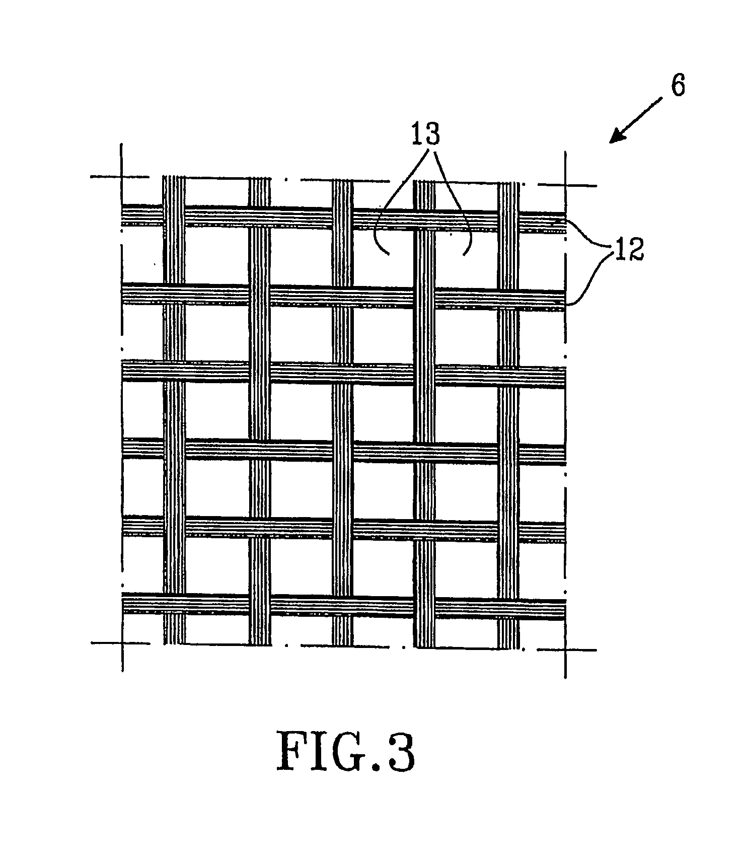
[0025] In FIG. 1 a main part 1 of a cellular phone transmitter unit is provided with a directional microphone pick up 2. The microphone pick up 2 is surrounded by a pick up housing 3 forming a chamber 4 having a predetermined cross-sectional area and a predetermined volume, which chamber 4 encloses the microphone pick up 2. The chamber 4 includes at least one sound passage opening 5, preferably a plurality of sound passage openings 5, 5′, 5″, each opening 5′, 5″, 5″′ provided with a wind noise reduction element 6. The number of wind noise reduction ...


PUM


Abstract

The present invention relates to wind noise reduction for a microphone (10) achieved by locating a microphone pick up (2) in a chamber (4) provided with at least one sound passage (5), wherein one or more elements (s) (6) is/are provided in the sound passage (s) (5) to decrease the speed of the air stream.

Description

BACKGROUND OF THE INVENTION [0001] The present invention relates to a transmitter portion of a portable electronic communication device and is concerned with reducing wind-noise produced by an undesired air stream blowing into a microphone. [0002] Conventionally, several types of so-called “non-directional microphones” have been used in transmitters provided in portable electronic communication devices such as cellular phones. However, although these microphones are considered to be less sensitive to wind-noise from air blowing into the microphone compared to so-called “directional microphones”, wind-noise is often still a problem. Therefore, noise cancelling algorithms are sometimes used to reduce this problem. However, a drawback is that due to power consumption, noise cancelling algorithms are not always suitable in portable electronic devices having limited battery capacity. [0003] Moreover, non-directional microphones also suffer from low signal to ambient ratio, whereby noise ...

Claims


Application Information

Patent Timeline
IPC IPC(8): H04R19/04H04R1/08
CPCH04R1/086H04R2410/07H04R2410/05
Inventor ANDERSON, DAVID
Owner SONY ERICSSON MOBILE COMM AB
Why Eureka
Try Eureka