IC receiver to minimize tracking error

a technology of ic receiver and tracking error, which is applied in the direction of electrical apparatus, electrical apparatus interference reduction, automatic control of pulses, etc., can solve the problems of reducing reception sensitivity, difficult to improve characteristic, and unsatisfactory interference characteristics

Inactive Publication Date: 2007-01-04
SONY CORP
View PDF15 Cites 65 Cited by
  • Summary
  • Abstract
  • Description
  • Claims
  • Application Information

AI Technical Summary

Problems solved by technology

If the tuning frequency fTN contains an error, the level of the received signal of the frequency fRX is low, thereby reducing the reception sensitivity.
Even when an antenna tuned circuit for use in the short-wave band is provided, however, as discussed above, the short-wave band is as broad as 1.8 MHz to 30 MHz, and the tracking error should also be considered.
If the antenna tuned circuit is an uninterlocked circuit, however, both the target frequency and the remaining frequencies are supplied to the following stages, resulting in an unsatisfactory interference characteristic.
In particular, if a frequency step in the reception frequency band is set small, the PLL does not have a wide loop bandwidth, and it is more difficult to improve the characteristic.
Meanwhile, in the antenna tuned circuit for use in the long- and medium-wave bands, if a padding capacitor (a capacitor for frequency adjustment) is adjusted so as to minimize the tracking error in the medium-wave band, the tracking error increases in the long-wave band.
Conversely, if the padding capacitor is adjusted so as to minimize the tracking error in the long-wave band, the tracking error increases in the medium-wave band.
Therefore, due to the tracking error, the reception sensitivity is reduced in the long or the medium-wave band.
If the antenna tuned circuit for use in the long- and medium-wave bands is an uninterlocked circuit in order to avoid such a reduction of the reception sensitivity, the above-described problems occur.
In this case, however, it is necessary to adjust the tuning frequency fTN for each receiver and to store the resultant data in the non-volatile memory, which wastes much time and labor, leading to increasing cost.

Method used


Image

  • IC receiver to minimize tracking error
  • IC receiver to minimize tracking error
  • IC receiver to minimize tracking error

Examples


Embodiment Construction

[0043] ① First Receiver

[0044] 1. Configuration and Operation of the Receiver

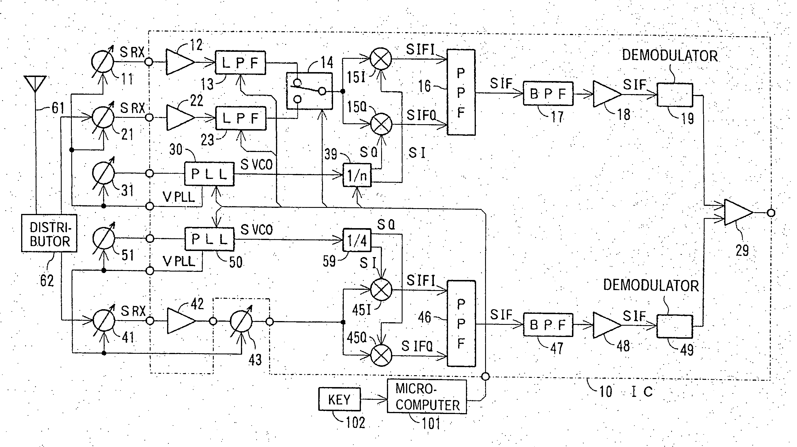
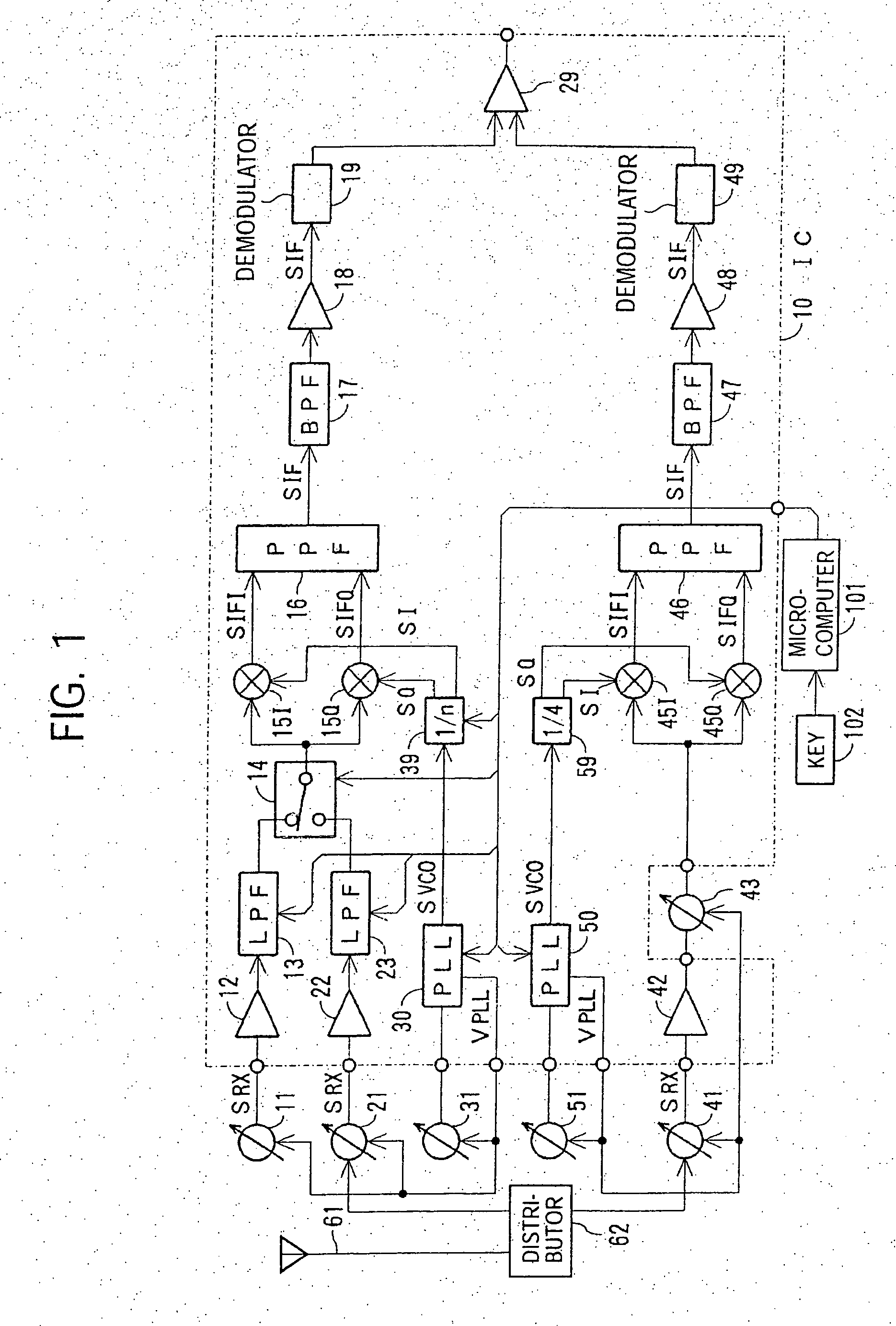
[0045]FIG. 1 shows an example in which the present invention is applied to a multi-band receiver for receiving long-, medium-, and short-wave band signals, and an FM broadcast band signal. In this example, the short-wave band is divided into four frequency sub-bands. In this example, the range and frequency step of the reception frequency bands at the long-, medium-, and short-wave bands and the FM broadcast band are shown in FIG. 3.

[0046] Although the relationship between the reception frequency and the local oscillation frequency, etc., is summarized later, the intermediate frequency for reception of long-, medium-, and short-wave band signals is 55 kHz, and the intermediate frequency for reception of FM broadcast band signals is 200 kHz.

[0047] In FIG. 1, a section 10 surrounded by a chained line indicates a monolithic IC of one chip. A microcomputer 101 serving as a system control circuit is connected...


PUM


Abstract

A multi-band receiver in which characteristics including a tracking error are improved is provided with a variable frequency oscillator circuit, a variable divider circuit (39) for dividing an oscillation signal (SVCO) of the variable frequency oscillator circuit, and mixer circuits (15I) and (15Q) for subjecting a received signal SRX to frequency conversion into an intermediate frequency signal (SIF) by a local oscillation signal (SLO). A divided output of the variable divider circuit (39) is supplied as the local oscillation signal (SLO) to each of the mixer circuits (15I) and (15Q). When a signal in a first frequency band is received, the division ratio n of the variable divider circuit (39) and the oscillation frequency of the variable frequency oscillator are changed to change the reception frequency in the first frequency band. When a signal in a second frequency band is received, at least the oscillation frequency of the variable frequency oscillator circuit is changed to change the reception frequency in the second frequency band.

Description

CROSS REFERENCE TO RELATED APPLICATIONS [0001] This application is a continuation of application Ser. No. 10 / 344,229 filed on Jun. 9, 2003, entitled “IC RECEIVER TO MINIMIZE TRACKING ERROR” which, in turn, claims priority under 35 U.S.C. 371 and 37 CFR 1.495 to PCT / JP02 / 05508, filed Jun. 04, 2002, which, in turn, claims priority to Japanese application No. JP2001-174197 filed Jun. 8, 2001.TECHNICAL FIELD [0002] The present invention relates to a receiver and an IC. BACKGROUND ART [0003] A typical double-conversion superheterodyne receiver has a configuration shown in FIG. 17. Specifically, a signal received by an antenna 61 is supplied to an antenna tuned circuit 201 to obtain a target reception frequency fRX which is then supplied to a first mixer circuit 203 via a high-frequency amplifier 202. The received signal is subjected to frequency-conversion by the first mixer circuit 203 into a first intermediate frequency fIF1 by a first local oscillation signal supplied from a first loc...

Claims


Application Information

Patent Timeline
Patent Type & Authority Applications(United States)
IPC IPC(8): H04B1/26H03L7/18H03L7/08H03L7/183H03L7/23H04B1/28H04B1/40
CPCH04B1/005H04B1/0057H04B1/406H04B1/0082H04B1/28H04B1/0075H04B1/26
Inventor OKANOBU, TAIWA
Owner SONY CORP
Why Eureka
Try Eureka