Device and Method for Vascular Tamponade Following Percutaneous Puncture

a technology of vascular tamponade and percutaneous puncture, which is applied in the field of devices and methods for vascular tamponade following percutaneous puncture, can solve the problems of posing additional risks, difficult to achieve, and relatively expensive, and achieves optimal results

Inactive Publication Date: 2007-01-04
CIVCO MEDICAL INSTR CO
View PDF21 Cites 13 Cited by
  • Summary
  • Abstract
  • Description
  • Claims
  • Application Information

AI Technical Summary

Benefits of technology

[0010] In one preferred exemplary embodiment, the mechanical pad connects to a vertical stem that fits into a socket in the mechanical arm and this socket includes the in-line micro-adjust screw mechanism. The central hole in the mechanical pad may be larger than the tip of a middle finger. The pad may be centered over the vessel by palpation with the middle finger while pressure is applied with all three fingers. The first and fourth finger rest on the mechanical pad while the vessel is felt (palpated) with the middle finger. This allows the important tactile feedback required to locate the vessel and apply an appropriate pressure based on experience. The force applied manually is then taken up by the mechanical arm set at an initial locked position and adjustment allowed by the micro-adjust screw. When ideal pressure is achieved as determined by palpation on the vessel, recording the pulse distal to the puncture site, experience of the user, and direct observation of the puncture site, hands are removed and routine procedures for observation and pressure release are followed. This device may allow the user to increase or decrease pressure on the anatomical site by using the micro-adjust screw at any time. The hole for the middle finger may be plugged to complete the compression surface by advancing a secondary surface plug when the fingertips are removed.
[0012] Another exemplary preferred embodiment may be achieved by temporary or fixed placement in the central area of the compression pad of an ultrasound transducer that is intended to image the underlying vessel. Using the ultrasound image may allow the user to correctly place and orient the compression surface over the desired vessel, to visualize flow through the vessel and to observe any leakage from the puncture site. All this may be done in real time and continuous ultrasound imaging may function as a monitor of performance during the compression period. This could be accomplished using a purpose built transducer that has a proper shape and surface for compression as an integral part of the casing / handle. Alternatively, an ideally shaped surface may be configured to receive (i.e. may function as a shoe) a more generic linear transducer that functions in the optimal frequency range. This shoe may be cleaned and sterilized for re-use or may be a single use disposable pre-sterilized item. A mechanical arm for holding the compression may be configured to securely grasp the ultrasound transducer and a mechanism may be included for micro-adjustment in the direction of the compression force similar to a purely manual embodiment. By using an ultrasound transducer as an integral part of the compression system, optimal results may be achieved. This is because the absolute minimum compression required to prevent leakage may be “dialed-in” using real time confirmation from the direct image, and any change in status may be immediately observed.

Problems solved by technology

However, these devices are themselves invasive, pose some additional risk, and are relatively expensive.
Also, it is more difficult than one might imagine because the compression force required varies from patient to patient, the area needs to be observed and observable, the area requiring compression is small, the vessel itself or the overlying tissues are somewhat mobile, and the angle of optimal compression may not be simply vertical but will vary greatly from patient to patient and procedure to procedure.
One downside of the manual compression method is that it fully occupies a nurse or technician preventing them from doing anything else for the length of time during which compression is applied.
Thus, expensive personnel are occupied for a dull, simple, repetitive and somewhat tiring task.
This device can be cumbersome to set up, covers the puncture site from view in an undesirable manner, and blocks normal tactile feedback.
This device also can be cumbersome to set up, interferes with the normal manual approach to vessel compression by blocking tactile feedback in the critical area, and is difficult to position and adjust.

Method used


Image

  • Device and Method for Vascular Tamponade Following Percutaneous Puncture
  • Device and Method for Vascular Tamponade Following Percutaneous Puncture
  • Device and Method for Vascular Tamponade Following Percutaneous Puncture

Examples


Embodiment Construction

[0031] Words of orientation as used herein such as “front,”“back” and “top” are used for exemplary convenience only as non-limiting examples of the orientation of features and are not intended to have any particular limiting effect.

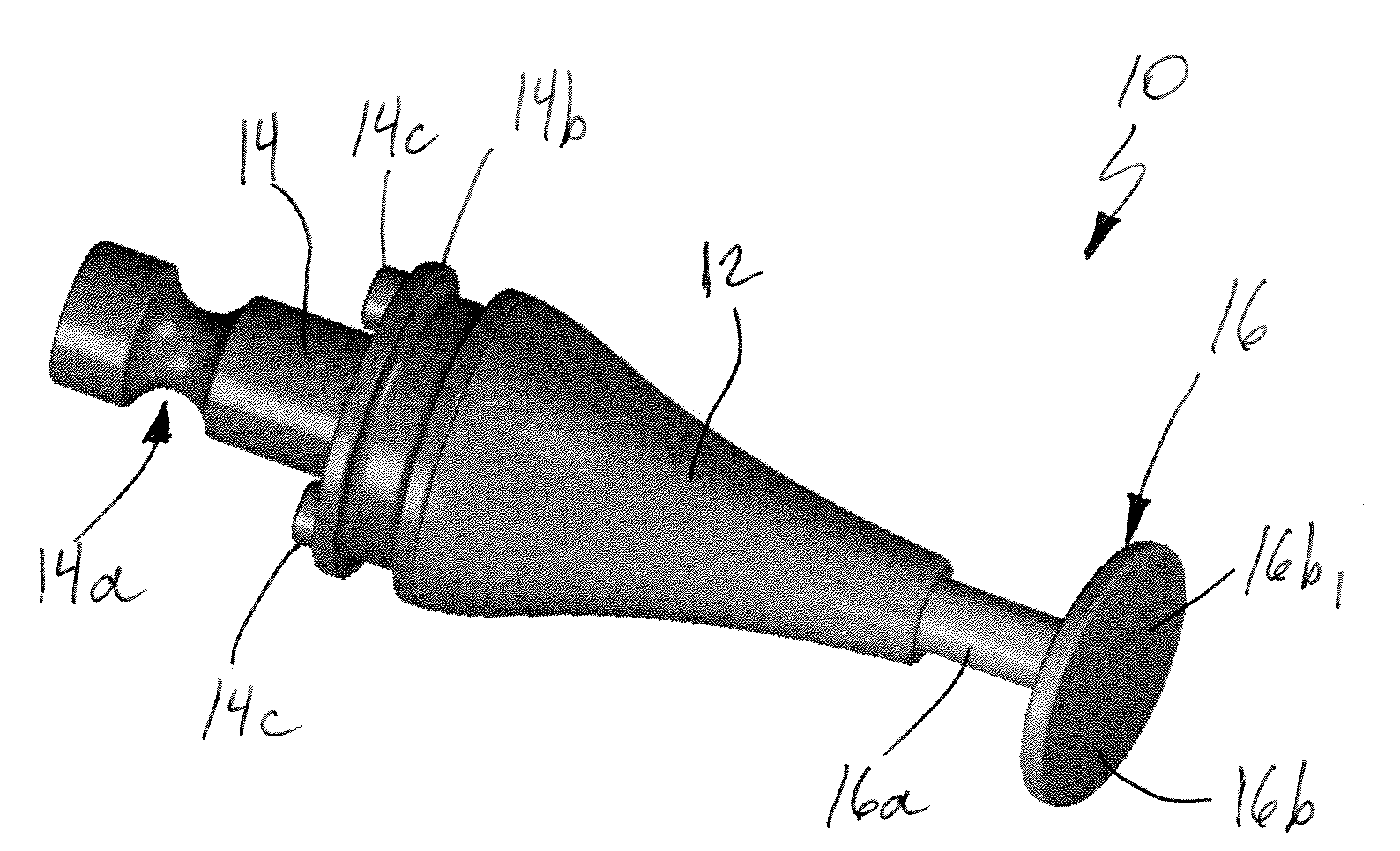
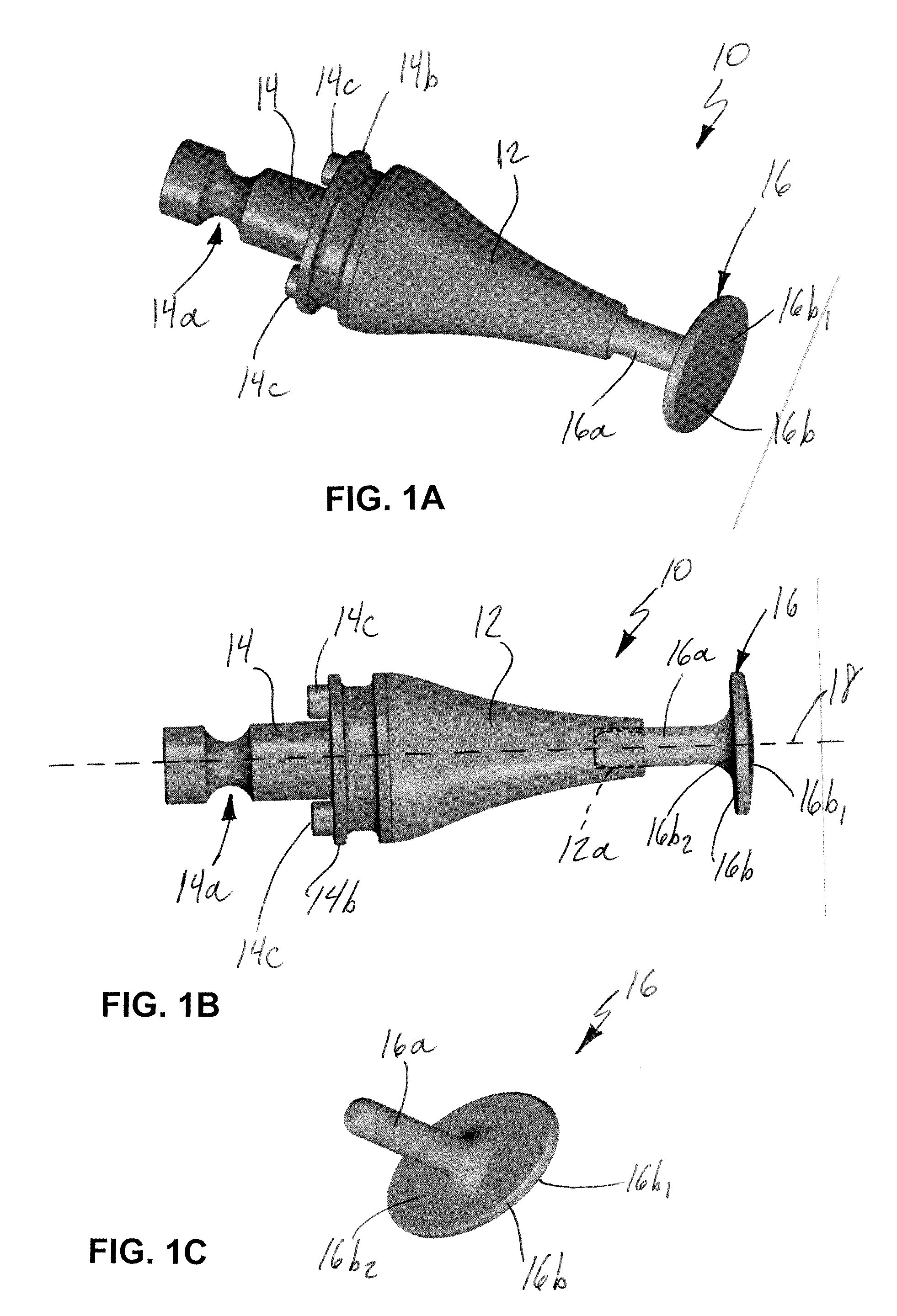
[0032] Referring initially to FIGS. 1A-1C, an exemplary embodiment of a vascular compression device 10 according to the present invention is shown. Device 10 includes a body 12 with a coupling portion 14 at a first free end thereof. Coupling portion 14 optionally may include a circumferential groove 14a therein. Body 12 may be demountably attached to coupling portion 14 proximate base portion 14b using screws 14c. Coupling portion 14 preferably is configured to be coupled to an articulating arm assembly as will be described later. A compression portion 16 is demountably coupled to a second free end of body 12. Compression portion 16 includes a stem 16a that is configured and dimensioned to be received and secured for example by friction fit in a hole 12a...


PUM


Abstract

A device for vascular tamponade includes a compression portion and a curvilinear articulating arm coupled to the compression portion. A method for vascular tamponade includes: manually applying a desired pressure proximate a puncture in a vessel by positioning a compression member to apply pressure against skin of a patient, the desired pressure permitting clot formation at the puncture; coupling the compression member to an object disposed in fixed relationship to the puncture; fixing the compression member in a position so that the desired pressure is maintained proximate the puncture without continuing to manually apply the desired pressure.

Description

CROSS-REFERENCE TO RELATED APPLICATIONS [0001] This application is a continuation-in-part of application Ser. No. 11 / 095,586 filed Apr. 1, 2005 and entitled “Support System for Use When Performing Medical Imaging of a Patient” which claims the benefits of Provisional Application No. 60 / 559,414 filed Apr. 2, 2004, Provisional Application No. 60 / 575,792 filed May 28, 2004, and Provisional Application No. 60 / 614,593 filed Oct. 1, 2004 under 35 U.S.C. § 119(e), and the entire contents of each of these applications are expressly incorporated herein by reference thereto. In addition, the benefits of Provisional Application No. 60 / 667,688 filed Apr. 4, 2005 and entitled “Device and Method for Vascular Tamponade Following Percutaneous Puncture” are claimed under 35 U.S.C. § 119(e), and the entire contents of this provisional application are expressly incorporated herein by reference thereto.FIELD OF THE INVENTION [0002] The invention relates to a device and method for applying compression t...

Claims


Application Information

Patent Timeline
Patent Type & Authority Applications(United States)
IPC IPC(8): A61M29/00
CPCA61B17/0057A61B2017/12004A61B17/132A61B19/26A61B90/50
Inventor WHITMORE, WILLET F. IIIWILSON, ROGER F.
Owner CIVCO MEDICAL INSTR CO
Why Eureka
Try Eureka