Acoustic shock wave attenuating assembly

a technology of attenuating assembly and shock wave, which is applied in the direction of protective equipment, transportation and packaging, weapons, etc., can solve the problems of increasing use of explosive devices, destruction of property and life, and sometimes disruption of explosive devices, etc., and achieve the effect of suppressing or attenuating the blast

Inactive Publication Date: 2007-01-11
BLASTGARD TECH
View PDF47 Cites 18 Cited by
  • Summary
  • Abstract
  • Description
  • Claims
  • Application Information

AI Technical Summary

Benefits of technology

[0013] It is another object of the present invention to provide materials for attenuating the effects of explosions or blasts that can be used for a variety of configurations and which are sufficiently flexible so that the material can be placed around any shape container or surface.
[0030] Additional objects and advantages of the present invention are to provide total reliability and effectiveness by using no moving or electrical components, and by not depending upon materials which must be without flaws, imperfections, or other defects. The material of the present invention can use any type of available materials which function to attenuate shock waves and which can enclose the attenuating material in cells or recesses. The material of the present invention provides substantial attenuation of all types of pressure waves on the source sides as well as the remote side of the pressure wave attenuating structure.

Problems solved by technology

Explosive devices are increasingly being used in asymmetric warfare to cause destruction of property and loss of life, particularly in urban areas or against transportation facilities.
These explosive devices can sometimes be disrupted but there often is not sufficient warning of an attack.
However, for an explosive device the waves produced are always shock waves.
Shock waves produce the highly damaging phenomenon known as blast.
Gases and solid crystalline materials are inherently poor pressure wave attenuators.
Scattering and dispersion thus produce more attenuation because they smear the discontinuity leading the shock wave, the result of which is a significant drop in pressure in the material.
This process has been shown to only provide a low level of attenuation over all, as the resultant acoustic wave emerging from the medium can ramp up again into a shock wave.
When it is required to protect objects that are not flat, such as garbage receptacles and containers, flat panels do not provide adequate protection for non-flat surfaces, and the rigid material is not capable of being bent to conform to a curved surface.

Method used


Image

  • Acoustic shock wave attenuating assembly
  • Acoustic shock wave attenuating assembly
  • Acoustic shock wave attenuating assembly

Examples


Embodiment Construction

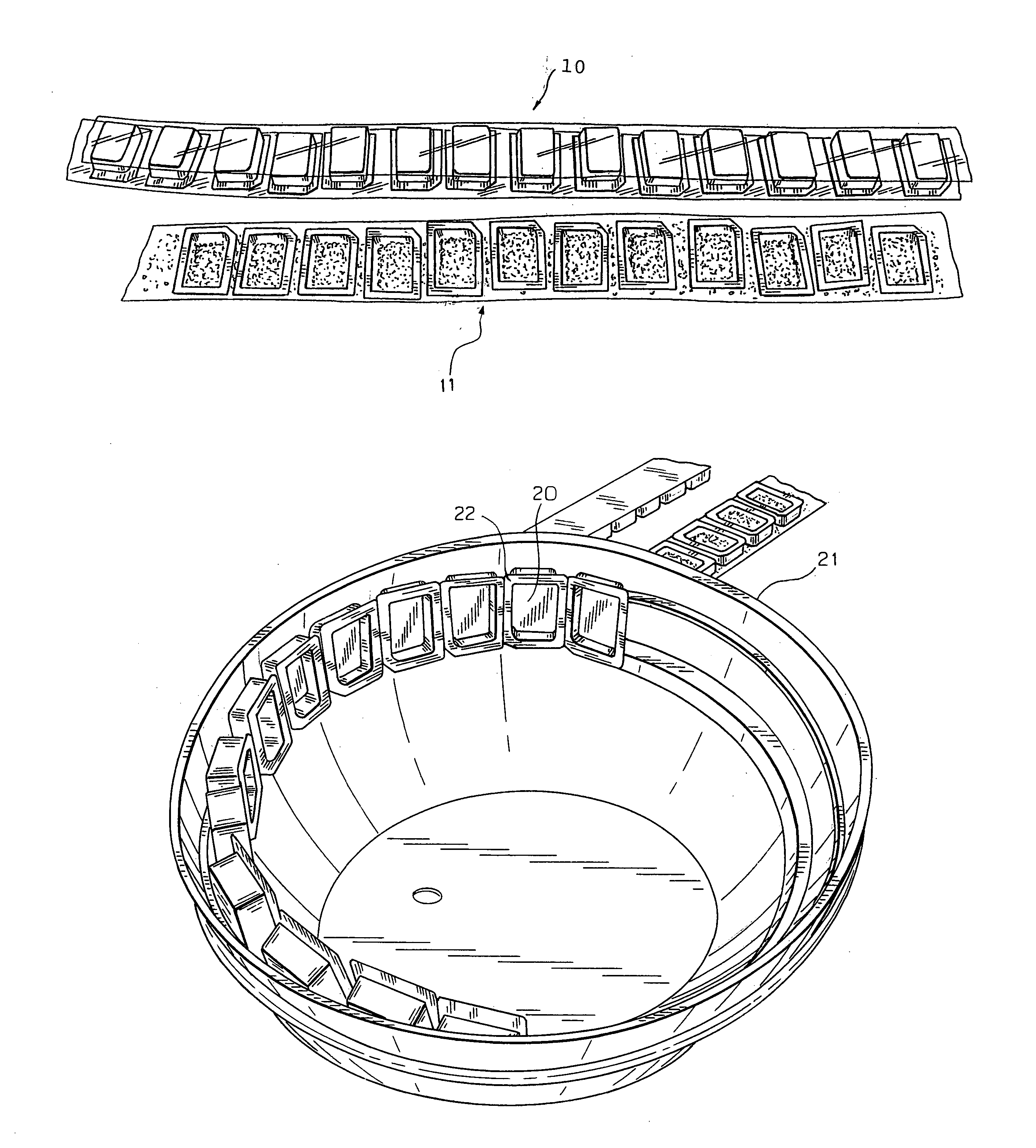
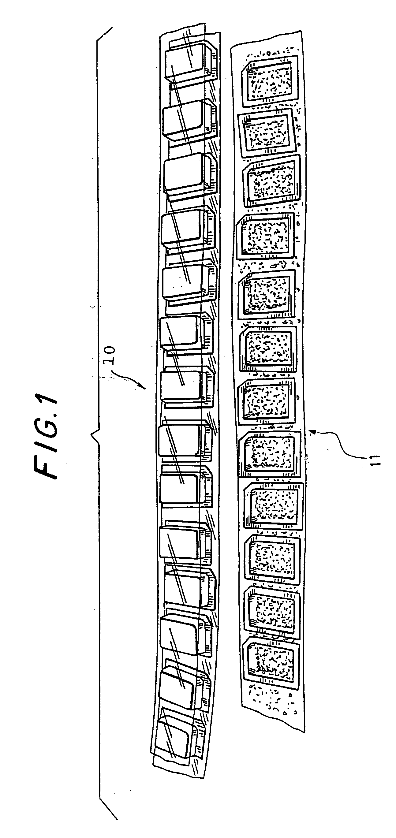
[0034]FIG. 1 shows tops 10 and bottoms 11 of the attenuating assembly prior to assembly. Once these cells of attenuating material are joined together as by adhesive means to form seams, the assembly can be cut at the seams to the desired dimensions.

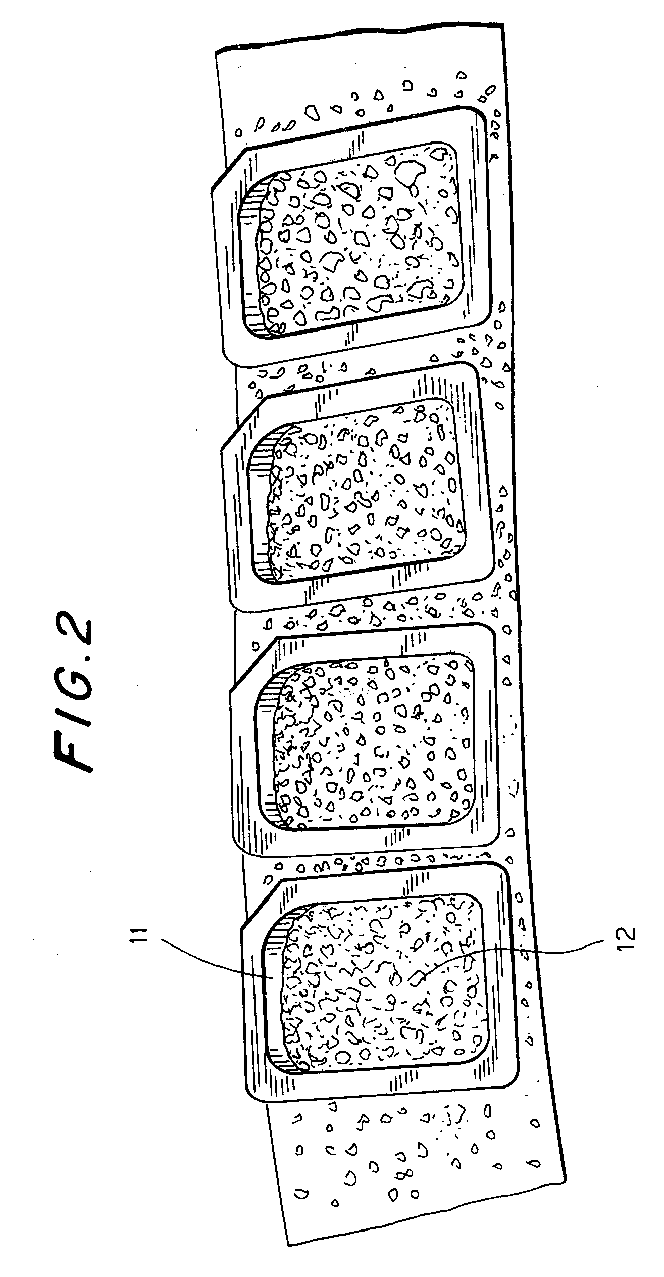
[0035]FIG. 2 shows a closer view of the bottoms 11 of the assembly. In this case the cells are filled with perlite.

[0036]FIG. 3 shows the assembly 20 installed in the interior of a dish 21, illustrating how the assembly can assume the shape of the surface it is to protect. The individual cells are joined at the seams 22, and the assembly can be cut at any of the seams to form a desired shape or size.

[0037] While the assembly has been illustrated with rectangular cells for retaining he shock attenuating material in place, the cells can be of any desired shape, including round, oval square, rectangular, polygonal, etc. The size of the cells is not critical other than to make them sufficiently small that the assembly can be cut to the des...


PUM


Abstract

An assembly for attenuating shock waves is made of two flexible sheets arranged one over the other and joined by a plurality of seams, the flexible sheets being confined to form cells or recessed when joined together. The seams are arranged so as to surround the cells or recesses in the sheets, and the cells or recesses are filled with a shock attenuating material.

Description

FIELD OF THE INVENTION [0001] The present invention relates to an improved assembly for attenuating pressure waves in order to mitigate undesirable effects of these waves. BACKGROUND OF THE INVENTION [0002] Explosive devices are increasingly being used in asymmetric warfare to cause destruction of property and loss of life, particularly in urban areas or against transportation facilities. These explosive devices can sometimes be disrupted but there often is not sufficient warning of an attack. This is becoming more so in a global scenario of suicide attacks and maximized mass casualties. [0003] Explosive devices produce blast fragments emanating both from the device casing and from material close to the point of explosion, so called secondary fragmentation. In addition explosive devices produce shock waves, which can be characterized by having a rise time that is a virtual discontinuity in the physical properties of the gas through which it propagates. It is possible that acoustic w...

Claims


Application Information

Patent Timeline
Patent Type & Authority Applications(United States)
IPC IPC(8): F41H5/02F42D5/045
CPCF42D5/05F42D5/045
Inventor WADDELL, JOHN L. JR.GORDON, JAMES F.
Owner BLASTGARD TECH
Why Eureka
Try Eureka