Wafer Support Tool for Heat Treatment and Heat Treatment Apparatus

a technology of support tool and heat treatment apparatus, which is applied in the direction of charging support, lighting and heating apparatus, furniture, etc., can solve the problems of difficulty in additional work, difficulty in working with work pieces into intricate shapes such as curved surfaces, and easy generation of burrs on the surface of grooves, so as to reduce the cost and facilitate the work of heat treatmen

Active Publication Date: 2007-01-11
SHIN-ETSU HANDOTAI CO LTD
View PDF10 Cites 363 Cited by
  • Summary
  • Abstract
  • Description
  • Claims
  • Application Information

AI Technical Summary

Benefits of technology

[0007] The present invention has been made in order to solve the above problem and it is an object of the present invention to provide a wafer support tool for heat treatment easy in workin

Problems solved by technology

Since limitation is, however, placed on a shape of a work piece in this method, it is difficult to work the work piece into an intricate shape such as a curved surface.
There also arises a problem that burrs are easily generated on surfaces of the grooves during cutting operation.
In addition, there arises a problem that difficulties are encountered in additional working for removing the generated burrs and in polishing for decreasing surface roughness of the grooves with which a wafer is brought in contact, so damages or slip dislocations occur on wafers in the cont

Method used


Image

  • Wafer Support Tool for Heat Treatment and Heat Treatment Apparatus
  • Wafer Support Tool for Heat Treatment and Heat Treatment Apparatus
  • Wafer Support Tool for Heat Treatment and Heat Treatment Apparatus

Examples


example 1

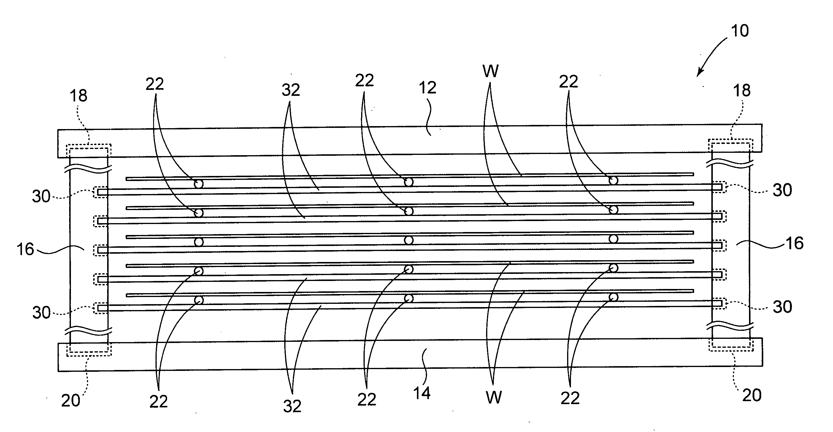
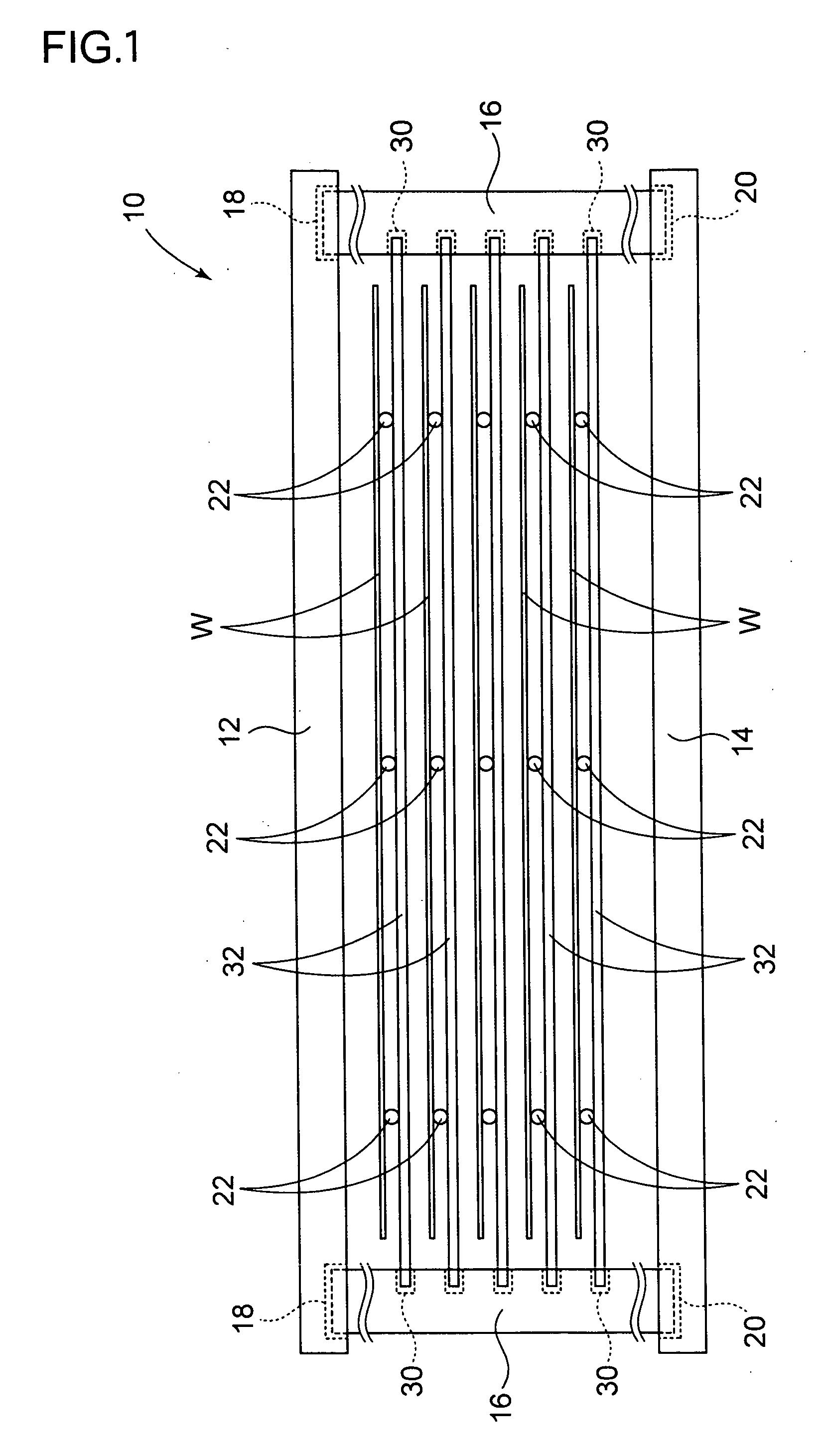
[0057] SiC was used as material of bases, support poles and pins to fabricate a wafer support tool for heat treatment described in FIGS. 1 and 2. In this case, each of the pins was prepared in a way such that a cylindrical body with a diameter of about 5 mm and a length of 10 mm was used, a contact section in the shape of a sphere with a diameter of about 5 mm was formed at the distal end thereof and a diameter of the proximal end thereof was worked to about 3 mm. Six slit-like pinholes provided radially were formed so that the central portions thereof were disposed at positions of 110 mm from the center of the pin holder.

[0058] Such a wafer support tool for heat treatment was used to conduct heat treatment of a CZ silicon single wafer with a diameter of 300 mm, a crystal orientation of , a conductivity type of p-type and a resistivity of about 10 Ωcm. Investigation was conducted about a state of occurrence of damages or slip dislocations in a contact portion with the wafer.

[0059]...

example 2

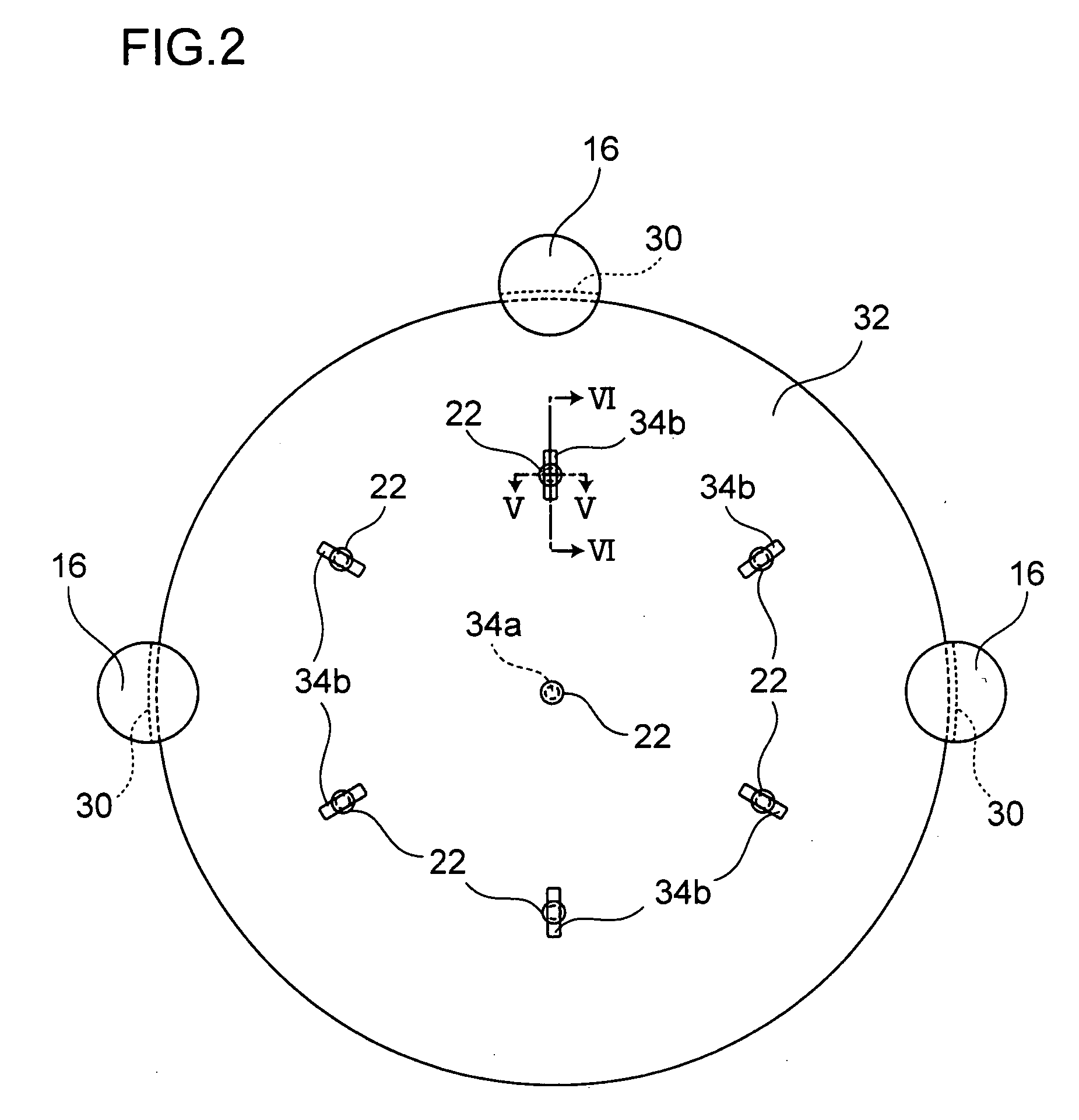
[0061] SiC was used as material of bases, support poles and pins to fabricate a wafer support tool for heat treatment as described in FIG. 1. The pin holder 32 had a diameter of 320 mm and a thickness of 1 mm, and nine slits 34b, each of which was a through hole with a width of 3.5 mm and a length of 9 mm and into each of which a pin was fitted, were formed radially on the pin holder 32, as shown in FIG. 14(a), wherein arrangement was such that three slits at positions 140 mm in radius at an angular spacing of 120 degrees, another set of three slits at positions 120 mm in radius at an angular spacing of 120 degrees and still another set of three slits at positions 60 mm in radius at an angular spacing of 120 degrees, and movable pins were inserted into all the nine slits 34b. In this case, each of the pins was formed from a cylindrical body having a diameter of 8 mm and a length of 10 mm, and a spherical contact section having a diameter of about 6 mm was formed at the distal end th...

example 3

[0066] In order to confirm an effect of movable pins, there was separately prepared a pin holder in which only pins at three sites 120 mm in radius with an angular spacing of 120 degrees were fixed as fixed pins 22f in the pin holder 32 used in Example 2 (FIG. 16(a)) with which heat treatment was conducted in the same conditions as in Example 2 and slip dislocations were observed with X-ray topography, results of which are shown in FIG. 16(b). In FIGS. 16(a) and 16(b), reference numeral 60 designates an arrow mark indicating a position of a notch of a wafer.

[0067] According to FIG. 16(b), occurrence of some slip dislocations were observed as compared with FIG. 14(b) in which the nine movable pins were used and it was found that the occurrence of the slip dislocations coincides with the positions of the fixed pins. Therefore, it was confirmed that movability in the contact portions between the wafer support member and the wafer has an effect of suppressing the slip dislocations.

[00...


PUM

PropertyMeasurementUnit
Temperatureaaaaaaaaaa
Forceaaaaaaaaaa

Abstract

The present invention provides a wafer support tool for heat treatment easy in working and capable of realizing reduction in cost without generating damages or slip dislocations that would be otherwise caused by high temperature heat treatment and a heat treatment apparatus. The present invention is directed to a wafer support tool for heat treatment comprising: a plurality of wafer support members for supporting a wafer to be heat treated; and a support member holder for holding the wafer support members, wherein the wafer support members each has a contact portion with the wafer, at least one of the contact portions being movable relative to the support member holder.

Description

TECHNICAL FIELD [0001] The present invention relates to a wafer support tool used in heat treatment of a wafer such as a semiconductor wafer, for example a silicon wafer, and to a heat treatment apparatus. BACKGROUND ART [0002] In a wafer support tool used for batch type heat treatment, there has been generally adopted a design that plural wafers are inserted and held in parallel to one another in grooves of a structure called a boat, which has support poles with the grooves. Especially in heat treatment at 1000° C. or higher, SiC is generally adopted as material of a wafer support tool because of its heat resistance and other properties. A method is adopted to cut grooves directly in the support poles with a diamond cutter or the like. [0003] Since limitation is, however, placed on a shape of a work piece in this method, it is difficult to work the work piece into an intricate shape such as a curved surface. There also arises a problem that burrs are easily generated on surfaces of...

Claims


Application Information

Patent Timeline
IPC IPC(8): B05B5/025H01L21/00H01L21/324H01L21/673H01L21/687
CPCH01L21/324H01L21/67109H01L21/6875H01L21/67309H01L21/67303H01L21/68H01L21/683
Inventor IMAI, MASAYUKI
Owner SHIN-ETSU HANDOTAI CO LTD
Why Eureka
Try Eureka