Finger Lever of a Valve Drive of a Combustion Engine

a technology of internal combustion engine and finger lever, which is applied in the direction of valve arrangement, mechanical control device, instruments, etc., can solve the problems of increasing the required installation space, and the previously mentioned finger lever is also built undesirably long, and achieves the effect of reducing the installation spa

Inactive Publication Date: 2007-01-11
SCHAEFFLER TECH AG & CO KG
View PDF7 Cites 23 Cited by
  • Summary
  • Abstract
  • Description
  • Claims
  • Application Information

AI Technical Summary

Benefits of technology

[0015] According to another aspect of the invention, it is proposed to have a tab-like projection extend from a top side of the crossbar of the outer arm in the region of the slide. This projection prevents undesired extension of the slide over the top side of the crossbar for the decoupled movement of the outer arm.
[0016] In addition, according to the invention the arm is to

Problems solved by technology

Here, it is also clear that this external loading of the slide unnecessarily increases the required installation space for the

Method used


Image

  • Finger Lever of a Valve Drive of a Combustion Engine
  • Finger Lever of a Valve Drive of a Combustion Engine

Examples


Embodiment Construction

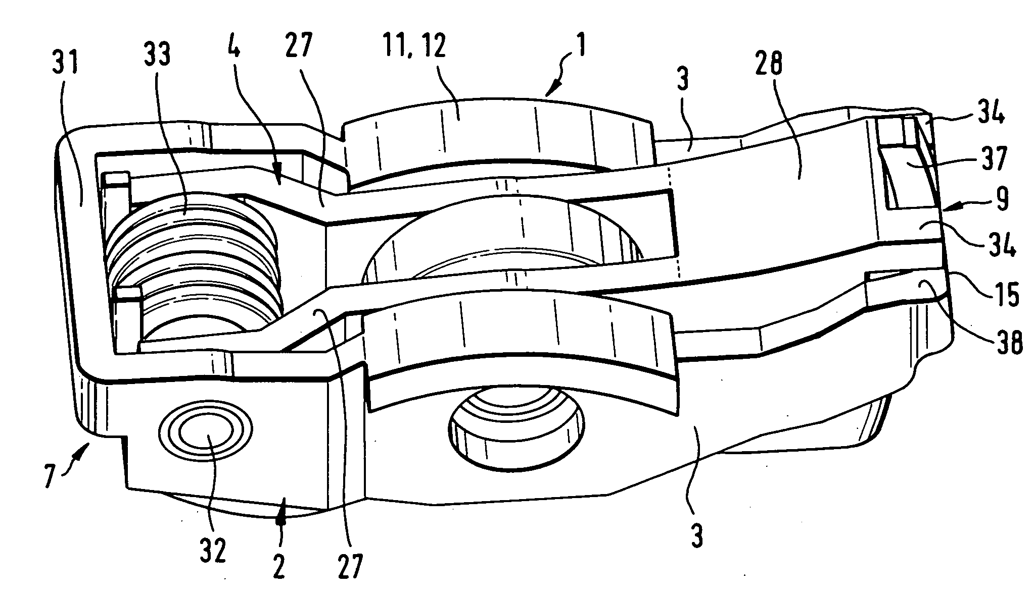
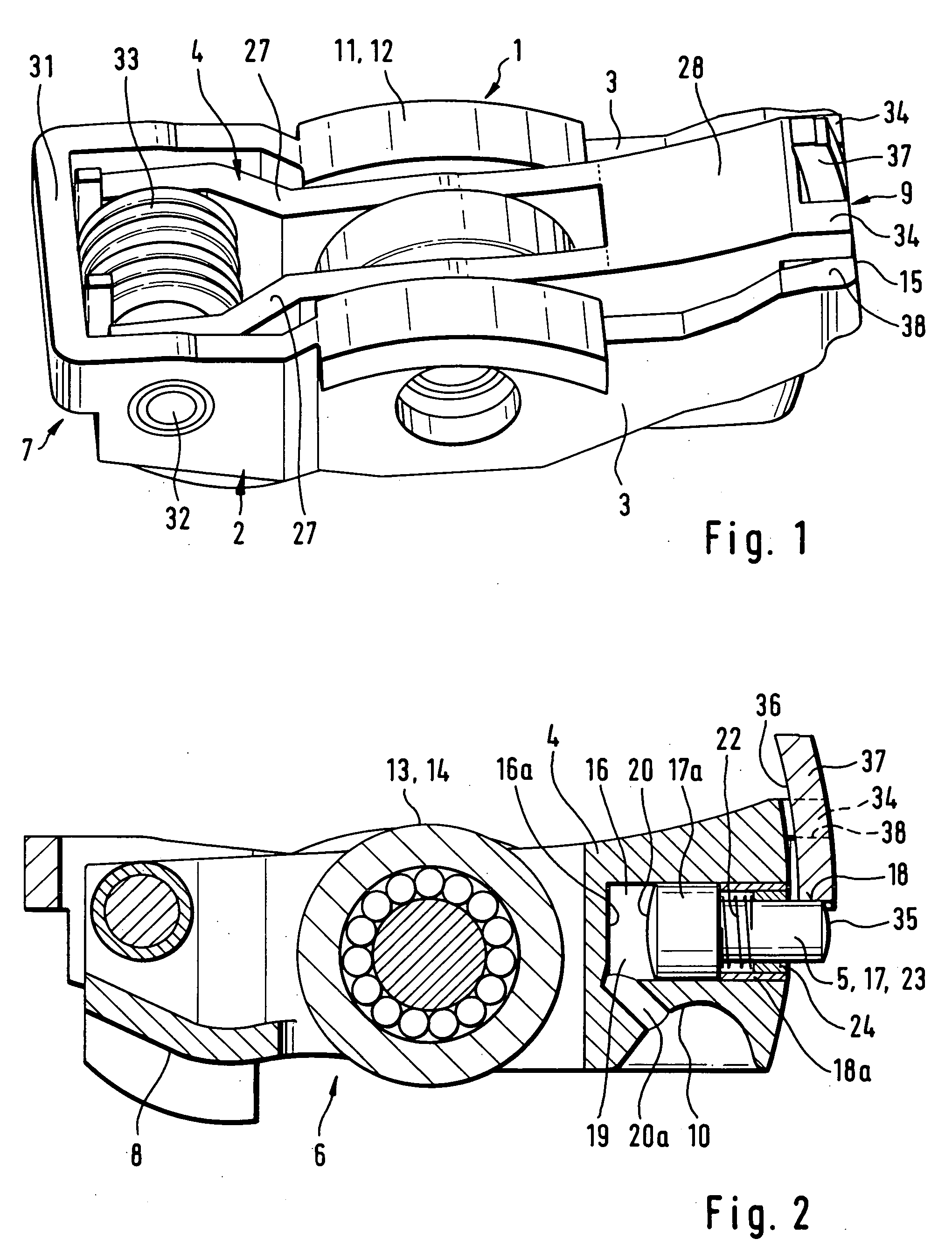
[0020] The Figures show a finger lever 1 that can be switched for different cam lifts. This arm includes an outer arm 2, which is connected to one end 9 by a crossbar 15. An inner arm 4 lies between limbs 3 of the outer arm 2 and is connected in an articulated way to the outer arm 2 in the region of the other end 7. For this purpose, the inner arm 4 moves on an axle 32, whose outer ends extend axially into boreholes of the limbs 3 of the outer arm 2.

[0021] A swivel-pin spring, which surrounds the axle 32 within the inner arm 4, is provided as the lost-motion spring 33. In the decoupled case of the outer arm 2 from the inner arm 4, a restoring motion is exerted through the action on the limbs of the inner arm, not explained in further detail, on the outer arm 2.

[0022] In the approximate region of the center, the limbs 3 of the outer arm 2 each have on their top side 11 a counter surface 12 for large lifting lobes. This counter surface 12 is embodied as a sliding surface. In contras...


PUM


Abstract

A finger lever (1) that can be switched for different cam lifts is provided. The finger lever includes an outer arm (2), between whose limbs (3) an inner arm (4) is pivotally mounted. Inside the inner arm (4), starting form one end (9), a blind borehole (16) is provided with a coupling element (5), which can be longitudinally displaced therein and which, in the event of coupling, can be displaced partially under a driver surface (18) of a crossbar (15) of the outer arm (2). Height stopping parts (34) are provided on the inner arm (4) in the form of a simple, finger-like extension of the inner arm (4) at the end (9) thereof which extend out over the crossbar (15).

Description

FIELD OF THE INVENTION [0001] The invention relates to a finger lever of a valve drive of an internal combustion engine, which can be switched to different lifts for at least one gas-exchange valve, with an outer arm between whose limbs an inner arm extends. Both arms can be pivoted relative to each other and can be coupled to each other through a coupling means, so that when coupled a larger valve lift is generated and when decoupled a smaller or 0 valve lift is generated. A stop for a gas-exchange valve is applied at one end on a bottom side of the finger lever and a complementary surface for a support element is applied on the other end. In addition, at least one counter surface for a large lifting lobe is provided on a top side of the outer arm and a counter surface for a small or 0 lifting lobe is provided on a top side of the inner arm. [0002] A finger lever of this type is already known from DE-OS 27 53 197. As coupling means, a catch is provided, which catches underneath the...

Claims


Application Information

Patent Timeline
IPC IPC(8): F01L1/18F01L1/34F01L13/00
CPCF01L1/185Y10T74/20882F01L13/0036F01L2001/186
Inventor SEITZ, JOACHIMRORIG, BODOOPIPARI, ANTEO
Owner SCHAEFFLER TECH AG & CO KG
Why Eureka
Try Eureka