Fuel cell vehicle

a fuel cell and vehicle technology, applied in the field of fuel cell vehicles, can solve the problems cramping the seating space of the occupants, and the inability to reliably protect the fuel cell stack against a load applied from a side of the vehicle perpendicular to the stacking direction of the fuel cell stack, etc., and achieve the effect of increasing the overall height of the floor panel and cramping the seating space in the cabin

Active Publication Date: 2007-01-11
HONDA MOTOR CO LTD
View PDF7 Cites 124 Cited by
  • Summary
  • Abstract
  • Description
  • Claims
  • Application Information

AI Technical Summary

Benefits of technology

[0014] The present invention was made in view of these circumstances and has as its object to provide a fuel cell vehicle that can reliably protect the fuel cell stack and fuel cell components against a load applied from outside without impairing comfort inside the cabin by raising the overall height of the floor panel and cramping the seating space in the cabin.
[0015] Another object of the present invention is to provide a fuel cell vehicle structure that can reduce measures for endurance for the hydrogen sensor under a condition that the fuel cell region is naturally ventilated.
[0016] Still another object of the present invention is to provide a fuel cell vehicle structure that can inhibit the influence of noise from a high voltage line on a low voltage line installed with the high voltage line.
[0017] A further object of the present invention is to provide a fuel cell vehicle structure that can eliminate the hydrogen sensor from the motor room even when the fuel cell is disposed under the floor panel to simplify the vehicle body structure.
[0018] A still further object of the present invention is to provide a fuel cell vehicle structure that can inhibit effects due to splashing up from a road surface onto the fuel cell stack and components thereof on the sub-frame attached to the bottom of the floor panel of the vehicle.

Problems solved by technology

However, in the case of such a conventional fuel cell vehicle, the fuel cell stack is disposed under the floor panel over a wide area in the vehicle width direction, leading to problems such as a rise in the overall height of the floor panel and cramping of the seating space of the occupants.
However, in this case reliably protecting the fuel cell stack against a load applied from a side of the vehicle perpendicular to the stacking direction of the fuel cell stack becomes an issue.
Similarly to the fuel cell stack, it is also an issue to dispose in the vehicle auxiliary components of the fuel cell such as a heater for cold starting and a voltage converter so as to reliably protect them against loads applied from outside the vehicle.

Method used


Image

  • Fuel cell vehicle
  • Fuel cell vehicle
  • Fuel cell vehicle

Examples


first embodiment

[0061] the present invention shall be described below with reference to the accompanying drawings.

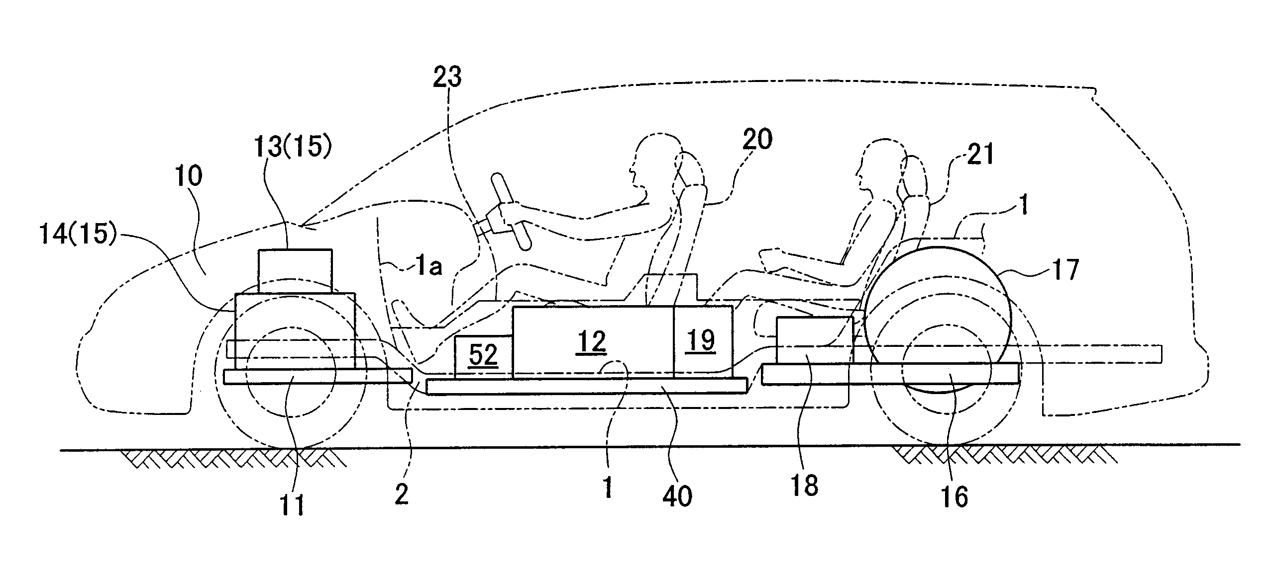
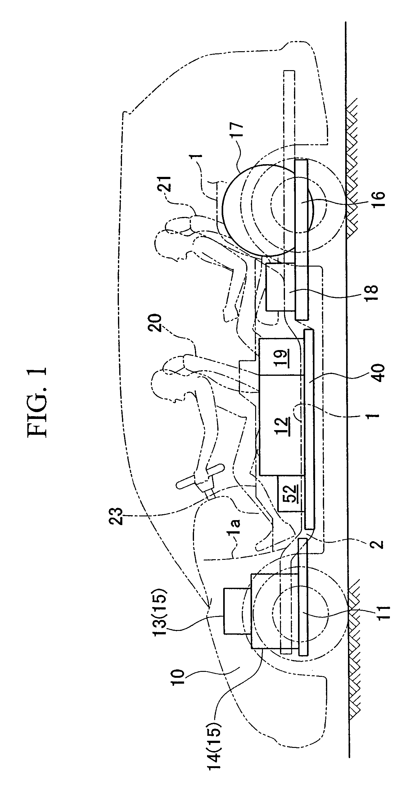
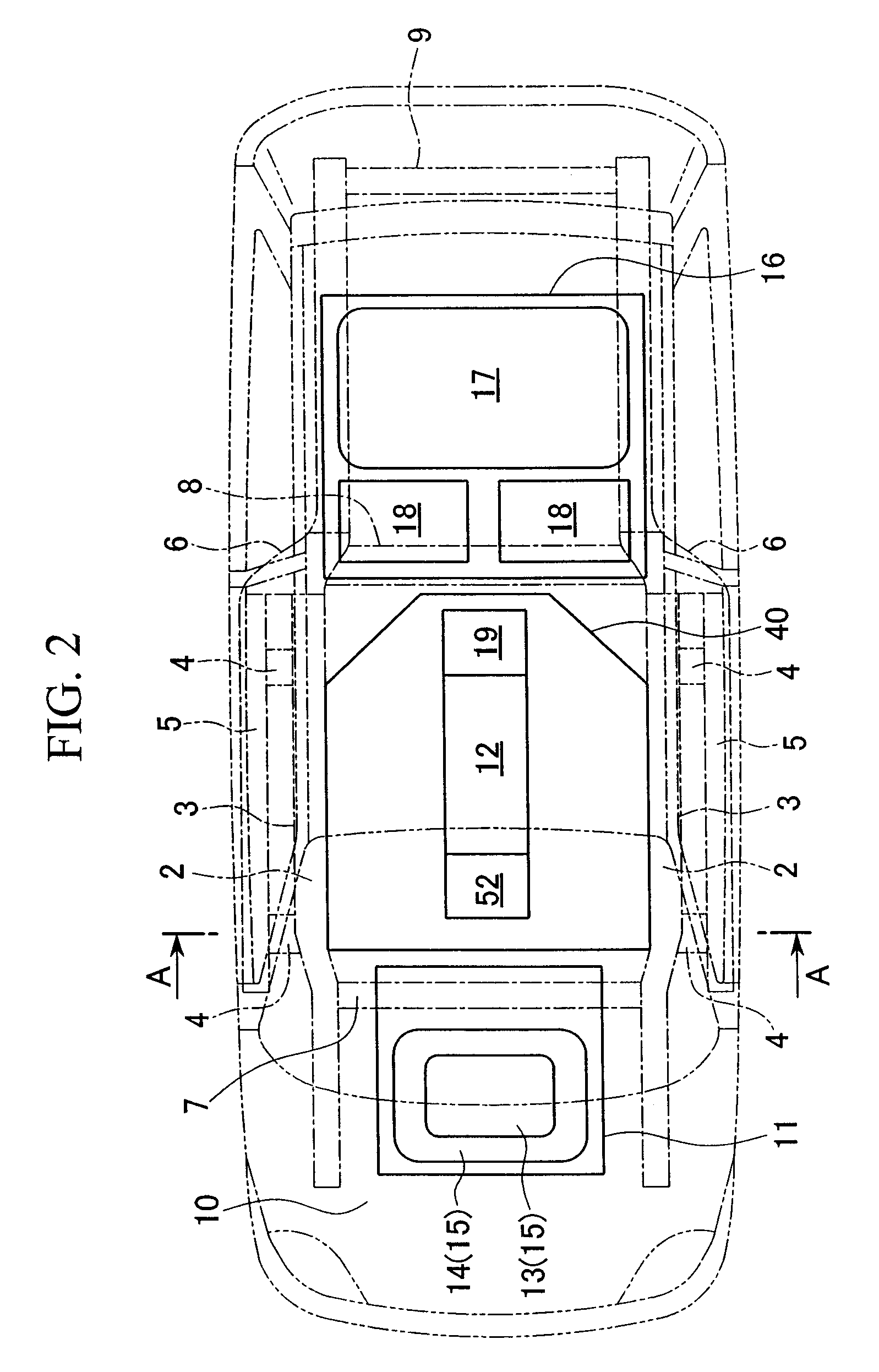
[0062] As shown in FIGS. 1 to 4, provided in the fuel cell vehicle are a pair of left and right side frames 2 forming the vehicle body skeleton member under a floor panel 1 from the vehicle body front portion to the vehicle body rear portion. A side sill 5 is joined via outriggers 4 to an outside wall 3 of each of the side frames 2. The rear end portion of each side sill 5 is connected so as to merge with the rear portion of the side frame 2 via an extension 6. Cross members 7, 8, and 9 that are the vehicle body skeleton members in the vehicle body width direction are coupled to the side frames 2.

[0063] A front sub-frame 11 is provided in a motor room 10 at the vehicle body front portion, and here is provided a pump motor unit 15 which includes a compressor 13 that feeds air to a fuel cell stack 12 and a drive motor 14 for traction.

[0064] A rear sub-frame 16 which is integrally equipp...

second embodiment

[0096] FIGS. 12 to 19 show the invention.

[0097] The basic structure of the fuel cell vehicle of the present embodiment is substantially identical to the first embodiment, differing from the first embodiment by the attachment structure of brackets 148 and 149 for attaching the fuel cell stack 12 to a sub-frame 140 and the joining structure of the frame elements of the sub-frame 140. In the second embodiment explained here, elements identical to those in the first embodiment are identified with the same reference numerals, and overlapping descriptions shall be omitted.

[0098] The basic structure of the sub-frame 140 is nearly identical to the first embodiment. However, the brackets 148 and 149 for attaching the fuel cell stack 12 to the sub-frame 140 each have an attachment base portion 80 that is joined to the sub-frame 140 as shown in FIGS. 12 and 13. The attachment base portions 80 extend so as to straddle the left and right sub-center frames 144, covering the top surfaces of the s...

third embodiment

[0107] the present invention shall now be described with reference to the drawings. In the following explanation, the orientations front, rear, right, and left, shall, unless specifically noted, be identical to orientations of the vehicle. Also, the arrow FR in the drawings indicates the front of the vehicle, the arrow LH the left side of the vehicle, and the arrow UP the top of the vehicle.

[0108] The fuel cell vehicle 201 shown in FIGS. 20 and 21 has mounted under the floor of the vehicle body a fuel cell stack 202 (hereinafter simply referred to as a fuel cell) that generates electricity by an electrochemical reaction between hydrogen and oxygen. The fuel cell vehicle travels by driving a drive motor 203 with electrical power generated by the fuel cell stack 202.

[0109] The fuel cell stack 202 is a well-known solid polymer electrolyte membrane fuel cell (PEMFC) formed by stacking a plurality of unit fuel cells (unit cells). Hydrogen gas is supplied to the anode side as fuel gas, a...


PUM


Abstract

A fuel cell vehicle includes: a vehicle body; a floor panel provided on the bottom of the vehicle body; a floor tunnel that is formed bulging upward in the center of the floor panel in the vehicle body width; a pair of front seats that are disposed on the floor panel, outside of the floor tunnel in the vehicle body width direction; center frames that support the floor tunnel, disposed at the center in the vehicle body width and extending along the vehicle body longitudinal direction; a sub-frame provided on the bottom of the floor panel and joined to the center frames; and a fuel cell stack mounted on the sub-frame and provided under the floor tunnel.

Description

BACKGROUND OF THE INVENTION [0001] 1. Field of the Invention [0002] The present invention relates to a fuel cell vehicle. [0003] Priority is claimed on Japanese Patent Applications No. 2005-200631, No. 2005-200632, and No. 2005-200633, No. 2005-200634, No. 2005-200635, and No. 2005-200636 filed Jul. 8, 2005, and Japanese Patent Application No. 2005-353358 filed Dec. 7, 2005, the contents of which are incorporated herein by reference. [0004] 2. Description of Related Art [0005] In a fuel cell vehicle, a fuel cell stack is formed by stacking a plurality of unit fuel cells, and the fuel cell stack is mounted below a floor panel. In this type of fuel cell vehicle, it has been proposed to attach the fuel cell stack to a sub-frame, and join this sub-frame to the vehicle body skeleton portion, such as side frames of the vehicle, from the vehicle body bottom (see, for example, Japanese Unexamined Patent Application, First Publication No. 2003-182624). [0006] Also, there is known a fuel cell...

Claims


Application Information

Patent Timeline
Patent Type & Authority Applications(United States)
IPC IPC(8): B60L8/00
CPCB60K1/04B62D25/025B62D25/20B62D25/2036Y02E60/50H01M8/04253H01M8/2485H01M2250/20Y02T90/32H01M8/04029H01M8/2484Y02T90/40Y02T10/7072
Inventor ONO, TOHRUOGAWA, TAKAYUKINAKASHIMA, AKIRANOZAKI, SHUJIROKATO, TAKASHISATO, TAKAHARUNAGUMO, KENJIFUKUMA, KAZUNORIMOORI, TAKANORI
Owner HONDA MOTOR CO LTD
Why Eureka
Try Eureka