Enhanced magnetron sputtering target

a magnetron sputtering and target technology, applied in the field of sputtering targets, can solve the problems of limited ability to improve these characteristics, reduced or lost benefits of magnetron sputtering systems, and difficult sputtering in magnetron sputtering systems, so as to improve sputtering rates, increase magnetic field passing, and increase plasma density

Inactive Publication Date: 2007-01-11
HERAEUS INC
View PDF12 Cites 5 Cited by
  • Summary
  • Abstract
  • Description
  • Claims
  • Application Information

AI Technical Summary

Benefits of technology

[0007] The present invention addresses the foregoing deficiencies of conventional sputtering targets by embedding magnets in the sputtering target. Specifically, one or more magnets are embedded in a back surface of the sputtering target and are oriented to increase the magnetic field passing through the sputtering target into the sputter chamber. By increasing the magnetic field in the sputter chamber, plasma density is increased which improves sputter rates and operating voltages can be reduced.

Problems solved by technology

However, the benefits provided by magnetron sputtering systems are reduced or lost when sputtering ferromagnetic target materials.
The high magnetic permeability and low pass-through flux characteristics of these materials make sputtering in a magnetron sputtering system difficult.
However, the ability to improve these characteristics is limited.
These solutions are also not ideal.

Method used


Image

  • Enhanced magnetron sputtering target
  • Enhanced magnetron sputtering target
  • Enhanced magnetron sputtering target

Examples


Embodiment Construction

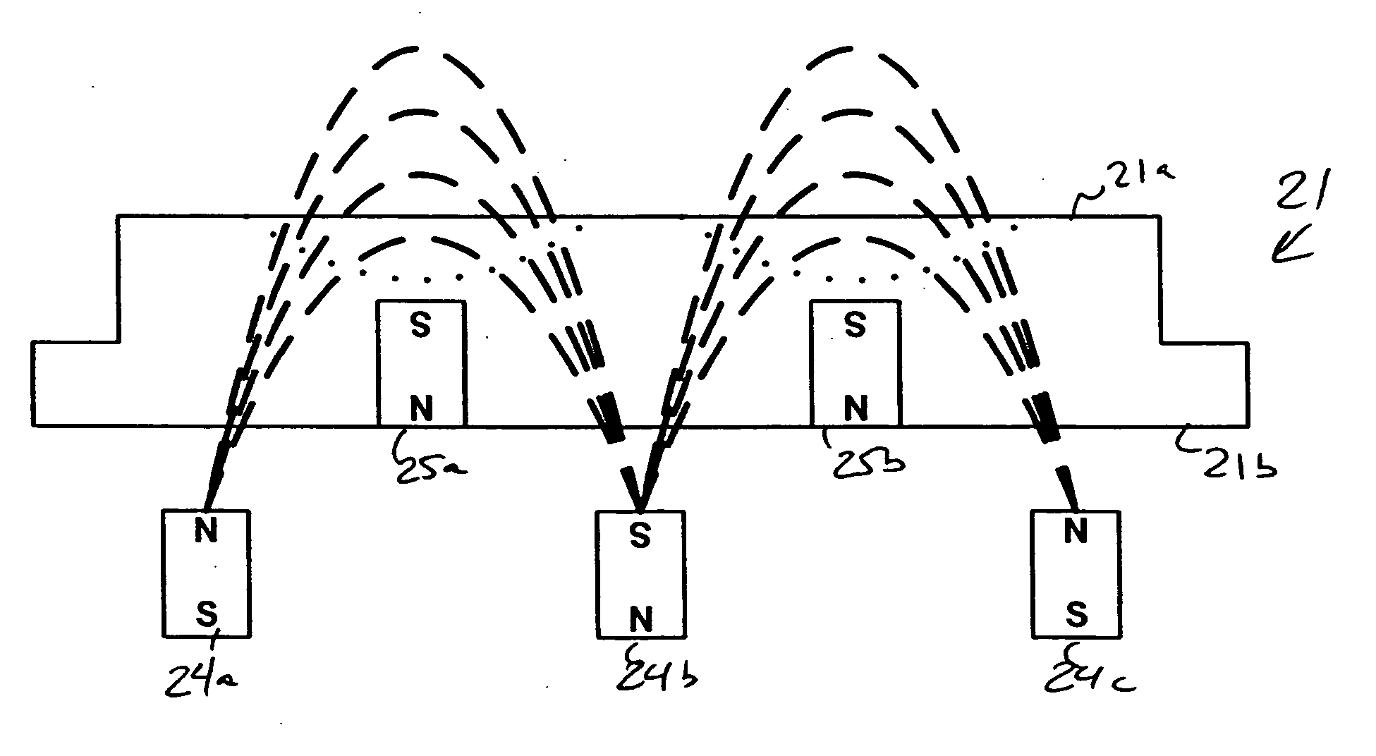
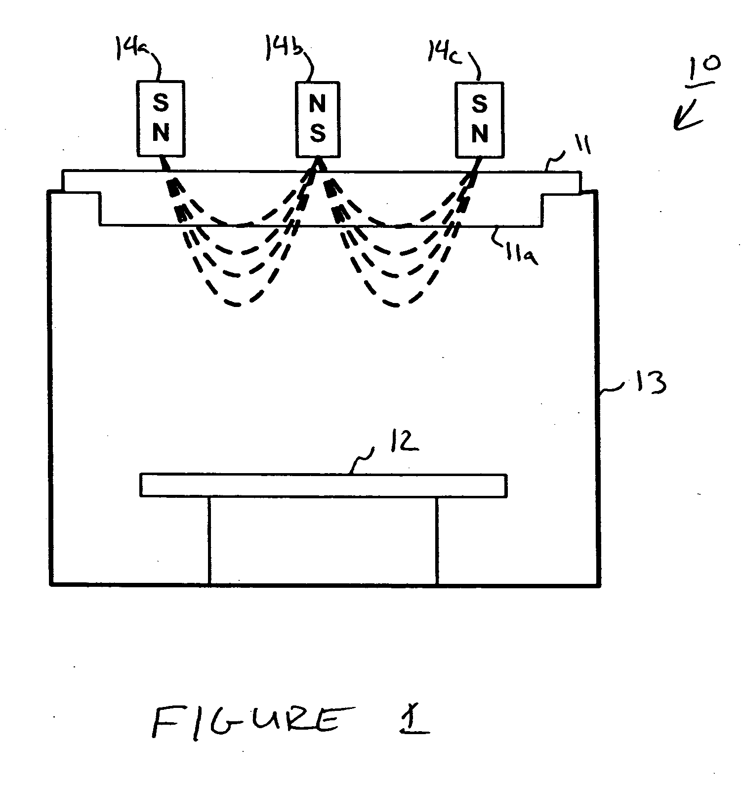
[0017]FIG. 1 is a diagram depicting components of magnetron sputtering system 10. Magnetron sputtering system 10 includes sputtering target 11 from which target material is sputtered onto the surface of substrate 12. During operation of the system, substrate 12 is placed in a sputter chamber formed by enclosure 13 and sputtering target 11. Magnetron sputtering system 10 further includes a magnetic array, which is depicted in FIG. 1 as magnets 14a to 14c, for generating a magnetic field over active surface 11a of sputtering target 11. It is noted that this depiction of magnetron sputtering system 10 is only one example of a magnetron sputtering system and does not include all of the components used in the operation of the system. One skilled in the art will recognize the applicability of the present invention to magnetron sputtering systems having configurations that differ from that shown in FIG. 1.

[0018] To sputter the target material from sputtering target 11, the sputter chamber...


PUM

PropertyMeasurementUnit
magnetic fieldaaaaaaaaaa
ferromagneticaaaaaaaaaa
depthaaaaaaaaaa

Abstract

An enhanced sputtering target is provided for use in a magnetron sputtering system. The sputtering target includes an active surface from which target material is sputtered and a back surface opposite the active surface. At least one magnet is embedded in the back surface of the target and is oriented to increase the magnetic field passing through the active surface of the target.

Description

FIELD OF THE INVENTION [0001] The invention concerns sputtering targets and in particular concerns sputtering targets enhanced for improved performance in magnetron sputtering systems. BACKGROUND OF THE INVENTION [0002] Diode sputtering systems are used to apply a film of target material to the surface of a substrate. An electric field is applied between a target and the substrate to generate a plasma within a sputter chamber. Ions from the plasma collide with the target and dislodge atoms of the target material. The dislodged atoms adhere to the surface of the substrate forming a film thereon. [0003] Magnetron sputtering systems improve the sputter rates of diode sputtering systems by using a magnetic field in addition to the electric field. Magnetron sputtering systems arrange a magnetic array behind the sputter target to generate a magnetic field over the active surface of the target. The magnetic field traps ions in the plasma near the active surface of the target, thereby incre...

Claims


Application Information

Patent Timeline
Patent Type & Authority Applications(United States)
IPC IPC(8): C23C14/00
CPCH01J37/3408H01J37/3461H01J37/3426
Inventor CHENG, YUANDA R.YANG, XINGBOKENNEDY, STEVEN ROGER
Owner HERAEUS INC
Why Eureka
Try Eureka