Method and apparatus for providing beams of nanodroplets for high sputtering rate of inert materials

a nanodroplet and high sputtering rate technology, applied in the field of nanodroplet beams for manufacturing and analytical, can solve the problems of low etching rate of ibm, no known use of electrospray nanodroplet beams for high sputtering rate of inert materials, and no use of focused electrospray beams for precision micromachining or three-dimensional profiling of organic samples via secondary ion mass spectrometry, etc., to achieve high sputtering rate ra

Inactive Publication Date: 2012-11-15
RGT UNIV OF CALIFORNIA
View PDF3 Cites 3 Cited by
  • Summary
  • Abstract
  • Description
  • Claims
  • Application Information

AI Technical Summary

Benefits of technology

[0009]A beam of charged nanodroplets is produced in vacuum using an electrospray source operating in the cone-jet mode. The droplets are accelerated with an electrostatic field, and directed against a solid surface, e.g. a silicon carbide target. We measure high sputtering yields and very high sputtering rates. This embodiment can be implemented in broad-beam applications for flood manufacturing, and focused beam applications for precision micromachining and secondary ion mass spectrometry (SIMS) of organic samples.

Problems solved by technology

However, there is no known use of electrosprayed nanodroplet beams for the high sputtering rate of inert materials, nor the use of focused electrospray beams for precision micromachining or three dimensional profiling of organic samples via secondary ion mass spectrometry.
Based on physical sputtering, the etching rates of IBM are lowest among subtractive techniques because of its beam's low molecular flux, which is limited by the space charge that develops between the plasma and accelerator screens.
Furthermore, the damage caused by these large projectiles is confined to molecular layers on the surface, and therefore it is possible to do depth profiling with these beams.
Unfortunately, cluster ion sources are not point sources and therefore these beams cannot be focused on a small spot.
Thus, cluster ion sources do not have lateral resolution.

Method used


Image

  • Method and apparatus for providing beams of nanodroplets for high sputtering rate of inert materials
  • Method and apparatus for providing beams of nanodroplets for high sputtering rate of inert materials
  • Method and apparatus for providing beams of nanodroplets for high sputtering rate of inert materials

Examples


Embodiment Construction

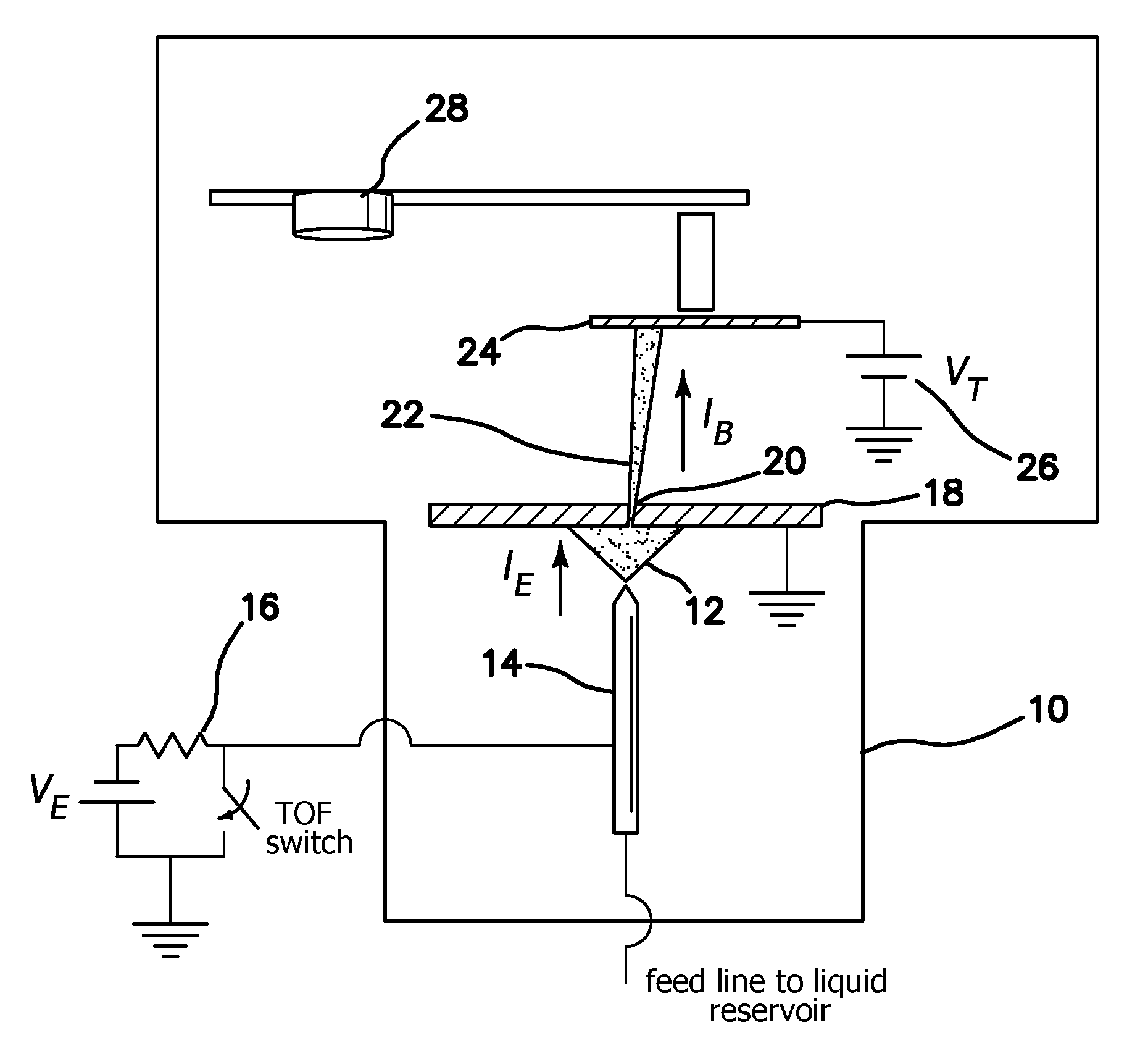
[0035]The produced beam of electrosprayed nanodroplets in the illustrated embodiments overcomes the problems of the prior art, because of their lower charge to mass ratio, the molecular fluxes of nanodroplet beams are orders of magnitude larger than those of ion beams at the same current density, and so are their sputtering rates. Furthermore, an electrospray source is a point source and a large fraction of its beam can be focused in a small spot using electrostatic lenses. Nanodroplet beams have molecular fluxes that are orders of magnitude larger than ion beams. This is due to the lower charge to mass ratio of the nanodroplets, which reduces the repulsive forces of the beam's space charge. Thus, the sputtering rates of nanodropet beams can be orders of magnitude larger than those of ion beams. In addition, an electrospray source is a point source and strong focusing of the beam in a submicrometric spot is possible.

[0036]In the illustrated embodiment, single-crystal silicon and pol...


PUM

PropertyMeasurementUnit
current densitiesaaaaaaaaaa
acceleration voltageaaaaaaaaaa

Abstract

A method for milling of a workpiece of inert material by nanodroplet beam sputtering includes the steps of providing aliquid; electrohydrodynamically atomizing the liquid to form charged nanodroplets; and directing the atomized charged nanodroplets onto the workpiece to selectively remove material. The method is used for broad-beam milling the workpiece of inert material, for precision micromachining and / or for three dimensionally profiling organic samples via secondary ion mass spectrometry. The liquid is electrosprayed in a cone-jet mode in a vacuum and average nanodroplet diameter, nanodroplet velocity, and molecular energy of the nanodroplets is adjusted by changing liquid flow rate and the acceleration voltage applied to the ionic liquid as it is atomized. Apparatus for performing the method are also included embodiments.

Description

BACKGROUND OF THE INVENTION [0001]1. Field of the Invention[0002]The invention relates to the field of methods and apparatus for providing nanodroplet beams for manufacturing and analytical applications (e.g. ion beam milling, focused ion beam micromachining, and three dimensional profiling of organic samples via secondary ion mass spectrometry).[0003]2. Description of the Prior Art[0004]It is known to use electrosprayed nanodroplets as projectiles for secondary ion mass spectrometry. It has also been proposed to use beams of electrosprayed droplets for the cleaning of surfaces. See, U.S. Pat. No. 6,768,119 B2, “Method and apparatus to produce ions and nanodrops from Taylor cones at reduced pressure”, by J. Fernandez de la Mora et. al. The art has developed a method to produce beams of nanodroplest, and to use these beams for the modification of surfaces. However, there is no known use of electrosprayed nanodroplet beams for the high sputtering rate of inert materials, nor the use o...

Claims


Application Information

Patent Timeline
Patent Type & Authority Applications(United States)
IPC IPC(8): H01J3/18H01J49/10
CPCG01N23/2258H01J37/08H01J37/3053H01J2237/31745H01J2237/0812H01J2237/31713H01J49/0004
Inventor GAMERO-CASTANO, MANUELMAHADEVAN, MAHESHSARMA, R. MAHADEVA
Owner RGT UNIV OF CALIFORNIA
Why Eureka
Try Eureka