Sputter chamber for coating a substrate

A sputtering chamber and substrate technology, applied in the field of sputtering chambers, can solve the problems of substrate layer thickness fluctuation, large loss, and different coating rates

Inactive Publication Date: 2007-10-03
アプライドマテリアルズゲーエムベーハーウントツェーオーカーゲー
View PDF5 Cites 2 Cited by
  • Summary
  • Abstract
  • Description
  • Claims
  • Application Information

AI Technical Summary

Problems solved by technology

On the other hand, near uninterrupted walls or near the surface of the substrate close to the plasma, the plasma suffers greater losses than at the edge of the substrate
Different

Method used


Image

  • Sputter chamber for coating a substrate
  • Sputter chamber for coating a substrate
  • Sputter chamber for coating a substrate

Examples


Embodiment Construction

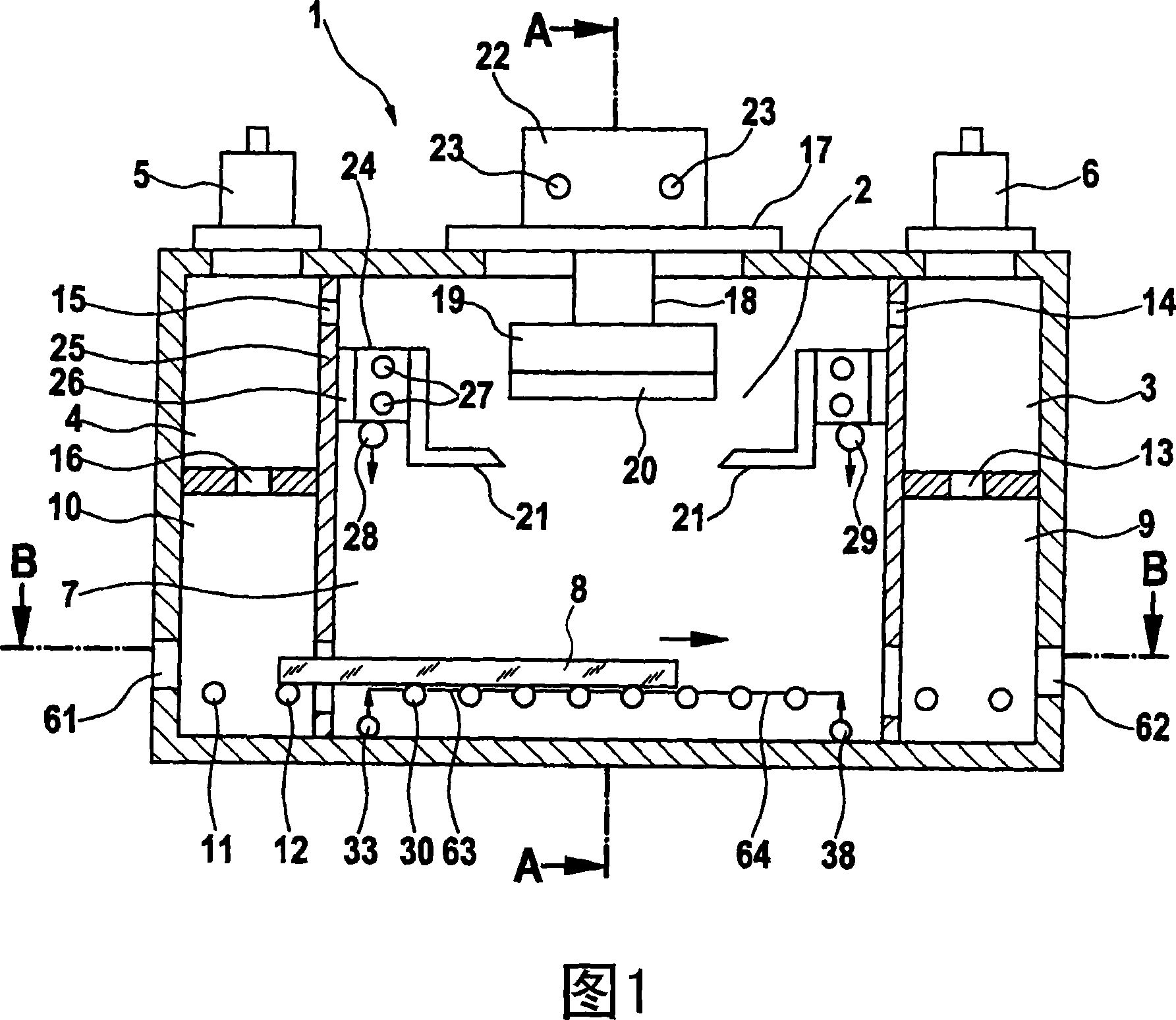
[0024] FIG. 1 shows a section through a sputtering chamber 1 with a cathode space 2 and two adjacent pumping spaces 3, 4 each equipped with preferably Pumps 5, 6 of turbo pumps. Auxiliary pumping chambers 9 , 10 are arranged below these pumping spaces 3 , 4 , and the substrate space 7 is located between the auxiliary pumping chambers 9 , 10 .

[0025] In the substrate space 7, a substrate 8, which may be a glass sheet, is conveyed from left to right on rollers 11, 12, 30. The pumping spaces 3 , 4 are connected via openings 13 to 16 to the substrate space 7 , the cathode space 2 or the auxiliary pumping chambers 9 , 10 .

[0026] The cathode 19 is arranged on a cover 17 which is placed on the sputtering chamber 1 via a mount 18 , and the target 2 is fastened on the cathode 19 . An anode 21 in the form of a hole is arranged opposite the cathode 19 . Arranged on the cover 17 is a cathode cap 22 comprising a cooling system 23 in which preferably water flows as coolant.

[0027...


PUM


Abstract

The invention relates to a sputter chamber for coating substrates, in which the so-called ''picture frame effect'' is eliminated or at least largely reduced. The thickness of the coating at the margin of a substrate hereby no longer deviates significantly from the thickness of the coating in the center of the substrate. This is attained thereby that the negative effect of the process gas-or of several process gases-which is introduced into the sputter chamber is equalized by an additional inert or reactive gas. At the margins of the substrates to be coated and on the substrate side facing away from the cathode thus an additional gas stream is generated, which is directed counter to the process gas stream.

Description

technical field [0001] The invention relates to sputtering chambers for coating substrates. Background technique [0002] In order to coat large-area substrates, the substrate is usually moved past a coating source located in a coating chamber. The substrate is continuously coated as it moves. [0003] In a coating plant, there may be several such sequentially arranged coating chambers in the coating plant. If the plant comprises both a feed and a feed-out, this is a so-called inline plant and is independent of the specific number of coating chambers. However, usually one or several coating chambers, as well as a pumping chamber and a lock chamber, which can be arranged according to the situation, are arranged in succession in the in-line equipment, and the coating chamber and these nearby chambers are conveyed device or gas connection channel. [0004] The conductance occurring in the transfer channel is in most cases low compared to the conductance of the coating chamb...

Claims


Application Information

Patent Timeline
IPC IPC(8): C23C14/34
CPCH01J37/3244H01J37/34H01J37/347H01J2237/3325
Inventor 罗兰·特拉斯里迈克尔·格斯勒艾伯特·卡斯特奈尔
Owner アプライドマテリアルズゲーエムベーハーウントツェーオーカーゲー
Why Eureka
Try Eureka