Magnetron sputtering target and magnetron sputtering system

a magnetron sputtering and target technology, applied in the direction of electrolysis components, vacuum evaporation coatings, coatings, etc., can solve the problems of target serious corrosion and target utilization rate reduction

Inactive Publication Date: 2010-10-07
HON HAI PRECISION IND CO LTD
View PDF5 Cites 3 Cited by
  • Summary
  • Abstract
  • Description
  • Claims
  • Application Information

AI Technical Summary

Problems solved by technology

However, the field of a target bombardment is not uniformly affected by density and the inequality of the magnetic lines of the mag

Method used


Image

  • Magnetron sputtering target and magnetron sputtering system
  • Magnetron sputtering target and magnetron sputtering system
  • Magnetron sputtering target and magnetron sputtering system

Examples


Embodiment Construction

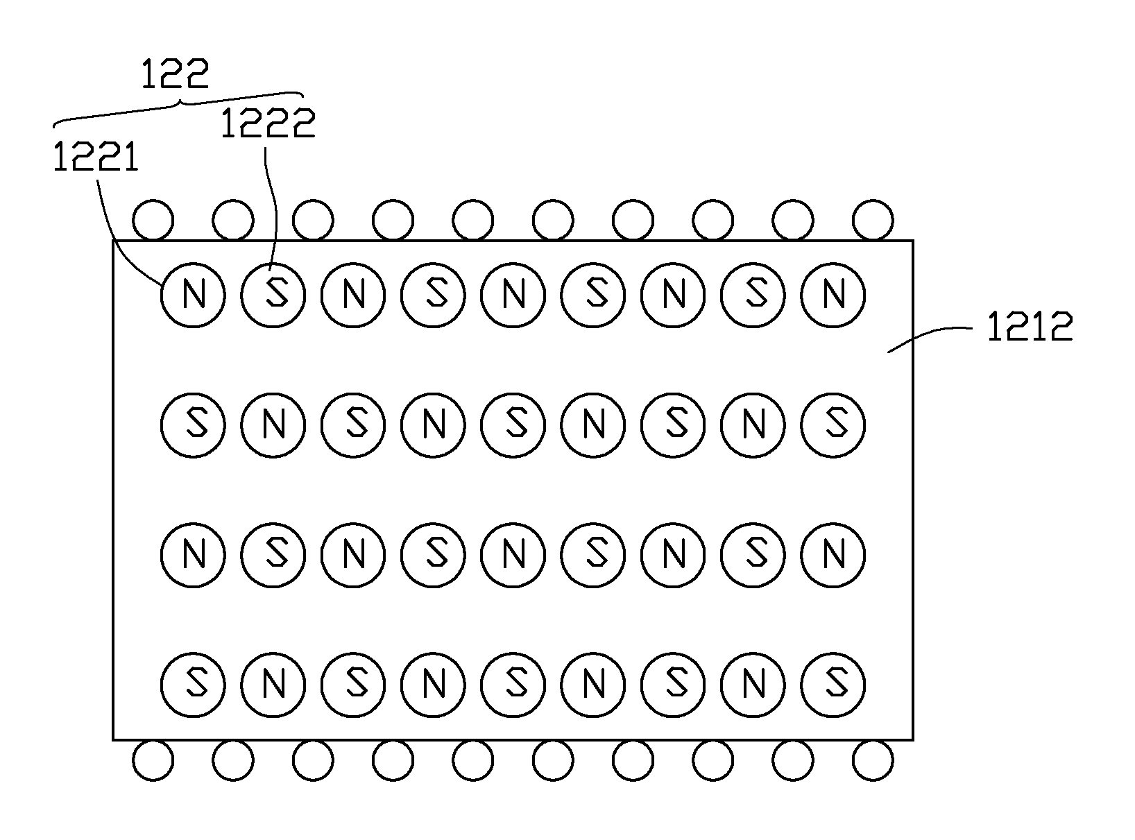
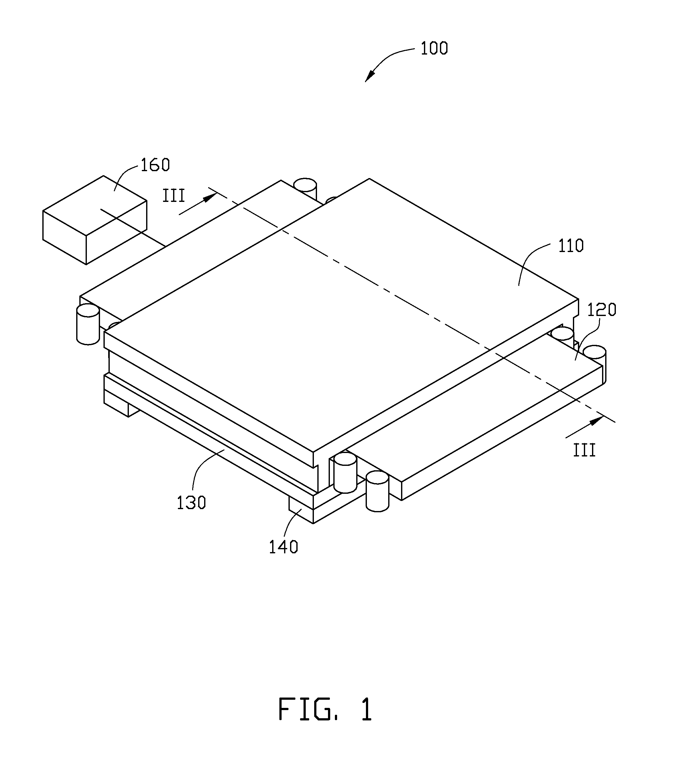
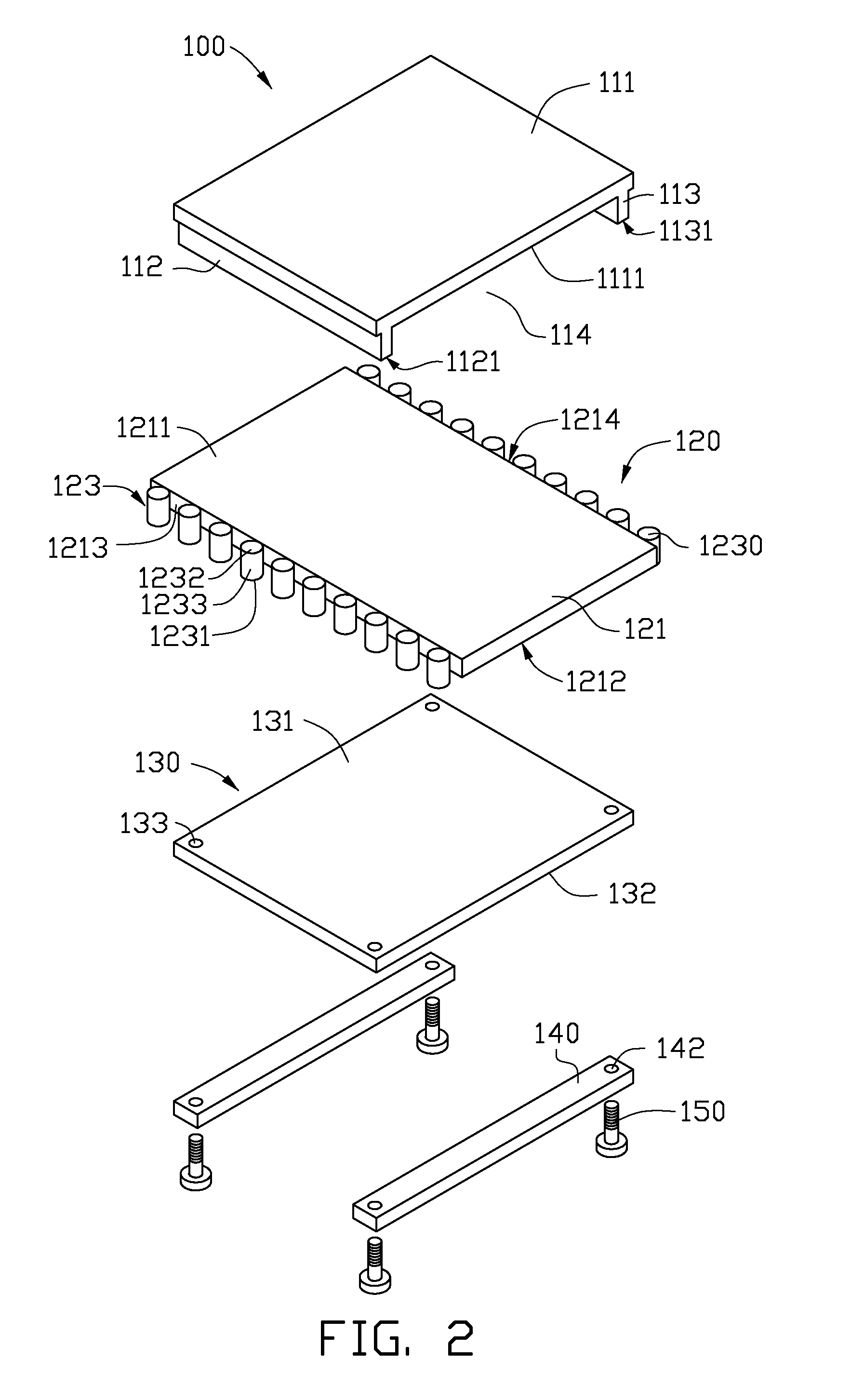
[0014]Referring to FIGS. 1-3, in a first exemplary embodiment, a magnetron sputtering target 100 includes a receiving base 110, a magnetron device 120, a target 130, two fixed plates 140, four fixed members 150 and a driving device 160.

[0015]The receiving base 110 receives the magnetron device 120 and fixes the target 130. The receiving base 110 includes a plate 111, a first wall 112 and a second wall 113 protruding from the plate 111. In the exemplary embodiment, the plate 111 is substantially rectangular and has a receiving surface 1111. The first protruding wall 112 and the second protruding wall 113 are defined in the receiving surface 1111 and extend along the lengthwise direction of the plate 111. The first protruding wall 112, the second protruding wall 113 and the receiving surface 1111 form a receiving space. Distance between the first protruding wall 112 and the second protruding wall 113 matches width of the magnetron device 120. Height of the first protruding wall 112 an...


PUM

PropertyMeasurementUnit
Distanceaaaaaaaaaa
Temperatureaaaaaaaaaa
Magnetic fieldaaaaaaaaaa

Abstract

A magnetron sputtering target comprises a magnetron device and a target positioned in a magnetic field of the magnetron device. The magnetron device comprises a metal plate, a plurality of first magnets and second magnets. A direction of the magnetic lines of the first magnets is opposite to that of the second magnets. The first magnets and the second magnets are embedded in the metal plate and arranged in a number of rows and columns. At least one first magnet is adjacent to a second magnet in one row, and at least one first magnet is adjacent to a second magnet in one column, therefore, there are magnetic lines in row direction and column direction exist in the magnetic field of the magnetron device.

Description

BACKGROUND[0001]1. Technical Field[0002]The present disclosure relates to magnetron sputtering devices, but more particularly, to a magnetron sputtering target and a magnetron sputtering system.[0003]2. Description of Related Art[0004]To increase the sputtering rate, a magnetron sputtering device uses the boundaries of magnetic fields to extend the trajectory of a electron, thereby changing the movement direction of the electron, therefore increasing ionization rate of the inert gases and making the best use of the energy of the electron.[0005]However, the field of a target bombardment is not uniformly affected by density and the inequality of the magnetic lines of the magnet of a target, thereby making part of the target seriously corrode, which results in the utilization rate of target being reduced.BRIEF DESCRIPTION OF THE DRAWINGS[0006]The components in the drawings are not necessarily drawn to scale, the emphasis instead being placed upon clearly illustrating the principles of ...

Claims


Application Information

Patent Timeline
IPC IPC(8): C23C14/35
CPCC23C14/3407C23C14/35H01J37/3455H01J37/3452H01J37/3408
Inventor PEI, SHAO-KAI
Owner HON HAI PRECISION IND CO LTD
Why Eureka
Try Eureka