Tandem rotary electric machine

Inactive Publication Date: 2007-01-11
DENSO CORP
View PDF0 Cites 9 Cited by
  • Summary
  • Abstract
  • Description
  • Claims
  • Application Information

AI Technical Summary

Benefits of technology

[0028] That is, according to the present invention, the secondary stator-rotor pair is placed at and close to the secondary rectifier device side. Because the stator core of the secondary stator-rotor pair having a large gyrating mass, a large weight, and a large heat capacity is placed at or close to the secondary rectifier device side, the secondary rectifier device can use, as heat sink, the stator core with a large heat capacity of the secondary stator-rotor pair through the housing of a rel

Problems solved by technology

Further, such a tandem rotary electric machine for vehicle can reduce its mount space in a vehicle when compared with a case in which two different non-tandem rotary electric machines are mounted separately on a vehicle.
Therefore the tandem rotary electric machine requires a complicated and large thermal dissipation mechanism for those rectifier components, and thereby causes a difficulty of efficiently cooling the rectifier components forming the rectifier device.
However, as described above, because the tandem rotary electric machine fo

Method used


Image

  • Tandem rotary electric machine
  • Tandem rotary electric machine
  • Tandem rotary electric machine

Examples


first embodiment

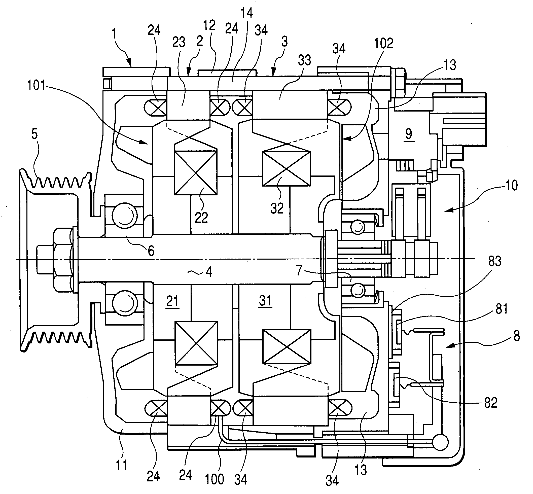
[0034] The entire configuration of a tandem electric rotary machine for vehicle (or a vehicle alternator), having a dual stator-rotor pair configuration, according to the first embodiment of the present invention will now be described with reference to FIG. 1.

[0035]FIG. 1 is a sectional view in a rotor shaft direction of the tandem electric rotary machine having a primary rotary electric machine and a secondary rotary electric machine arranged in tandem configuration according to the first embodiment.

Entire Configuration of the Tandem Electric Rotary Machine of the First Embodiment

[0036] In FIG. 1, a housing 1 comprises a front housing 11, a center housing 12, and a rear housing 13. Those housing components 11, 12, 13 of the housing 1 are fixed tightly together by a through bolt 14. A rotor shaft 4 is supported to the housing 1 through bearings 6 and 7. A pulley 5 is fixed to the front end part of the rotor shaft 4 that protrudes from the front end surface of the housing 1. A rec...

second embodiment

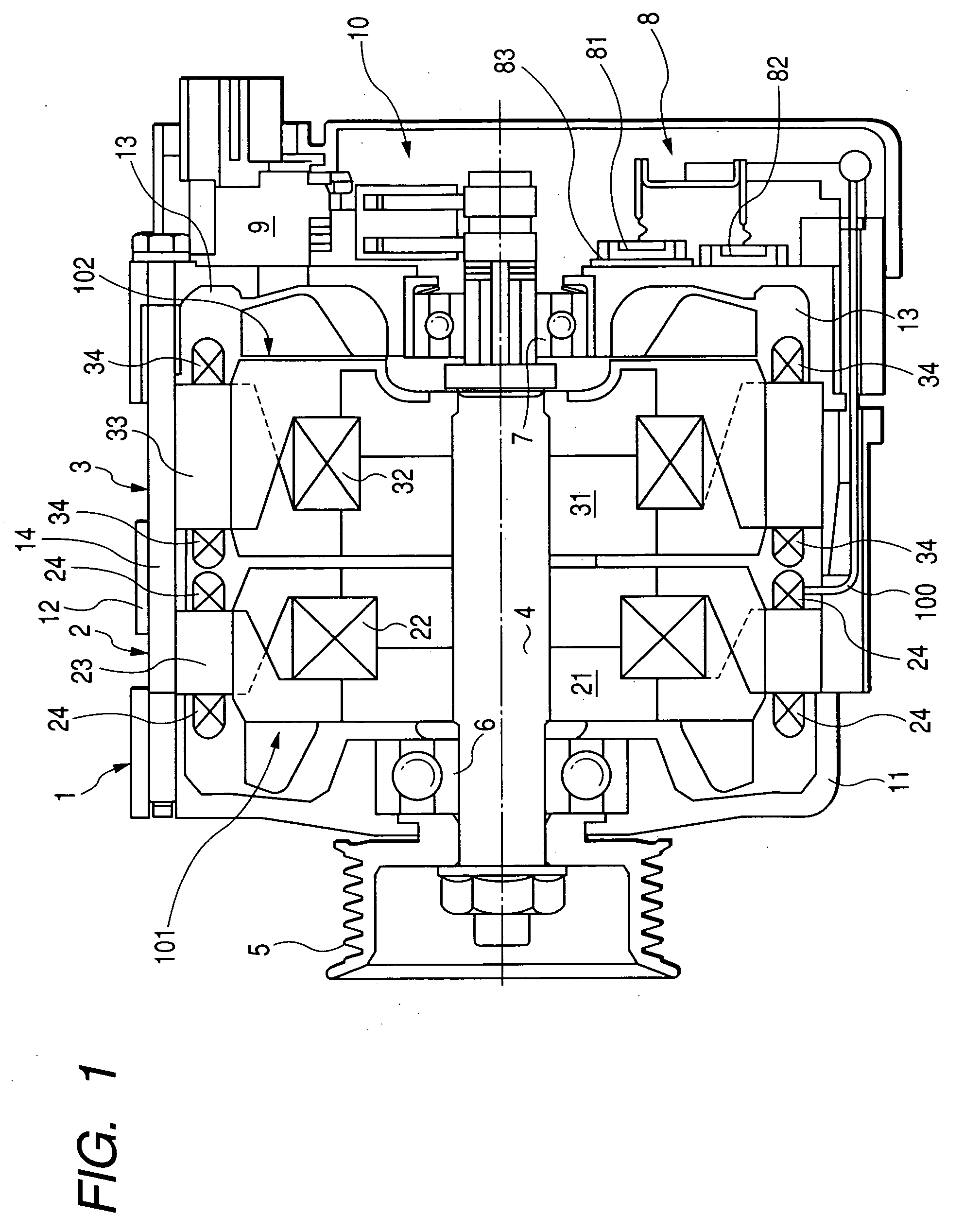
[0050] The entire configuration of a tandem electric rotary machine for vehicle (or the vehicle alternator) according to the second embodiment of the present invention will now be described with reference to FIG. 2. FIG. 2 is a sectional view in a rotor shaft direction of the tandem electric rotary machine of the second embodiment.

[0051] The tandem electric rotary machine for vehicle according to the second embodiment is basically same in configuration of the tandem electric rotary machine for vehicle of the first embodiment. Accordingly, a difference configuration and operation between the first embodiment and the second embodiment will be explained.

[0052] In FIG. 2, reference character 8A designates a rectifier device for the secondary rotary electric machine (or the secondary stator-rotor pair) 3, which is capable of rectifying output current from the secondary rotary electric machine 3. The rectifier device 8A for the secondary rotary electric machine 3 is mounted on the front...

third embodiment

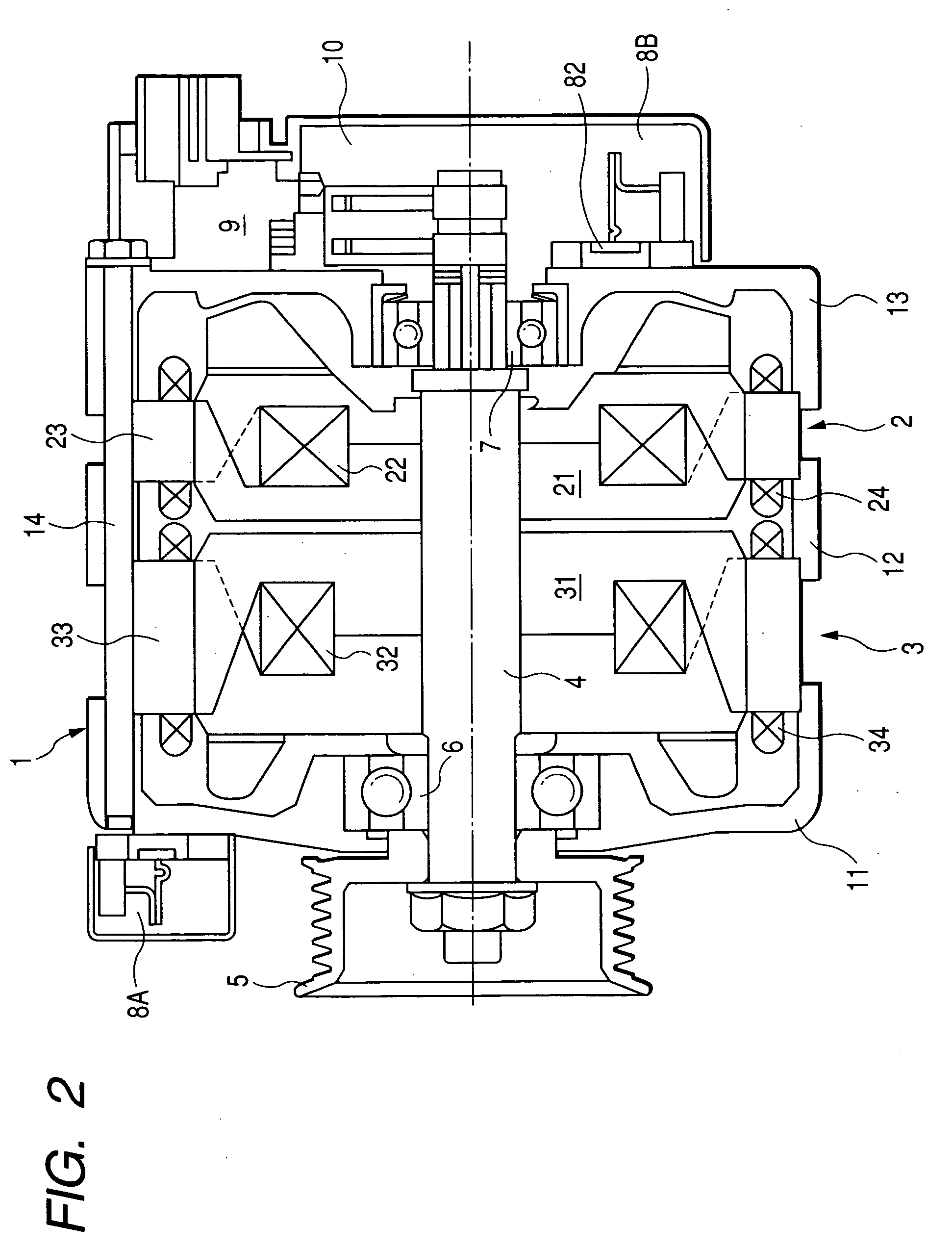
[0055] The entire configuration of a tandem rotary electric machine for vehicle (or the vehicle alternator) according to the third embodiment of the present invention will now be described with reference to FIG. 3. FIG. 3 is a sectional view in a rotor shaft direction of the tandem rotary electric machine of the third embodiment.

[0056] The tandem rotary electric machine for vehicle according to the third embodiment is basically same in configuration of the tandem rotary electric machine for vehicle of the first embodiment and the second embodiment. Accordingly, one of the differenced in configuration between the third embodiment and the first and second embodiments will be explained.

[0057] The randel type rotor core 21 of the primary rotary electric machine (or the primary stator-rotor pair) 2 comprises a pair of half cores 201 and 202. The randel type rotor core 31 of the secondary rotary electric machine (or the secondary stator-rotor pair) 3 comprises a pair of the half cores 2...


PUM


Abstract

A tandem rotary electric machine, to be applicable to various types of mobile bodies such as vehicles, is equipped with a primary rotary electric machine and a secondary rotary electric machine arranged in tandem mechanism. In the tandem rotary electric machine, heat energy generated by positive diodes and negative diodes forming one or more rectifier devices is dissipated to a stator core of the secondary rotary electric machine. The stator core of the secondary rotary electric machine acts as a heat sink through the housing. The stator core of the secondary rotary electric machine has a less frequency use, and a large size and a large weight than those of the primary rotary electric machine of high frequent and normal is used as a heat sink in order to prevent the temperature rise of the positive diode and the negative diode of the rectifier devices.

Description

CROSS-REFERENCE TO RELATED APPLICATIONS [0001] This application is related to and claims priority from Japanese Patent Applications No. 2005-201765 filed on Jul. 11, 2005 and No. 2006-28534 filed on Feb. 6, 2006, the contents of which are hereby incorporated by reference. BACKGROUND OF THE INVENTION [0002] 1. Field of the Invention [0003] The present invention generally relates to a tandem rotary electric machine applicable to various applications, for example, movable bodies such as vehicles, and in particular relates to a tandem rotary electric machine in tandem mechanism having a single rotor shaft and plural pairs of a stator and a rotor, each of the stator rotor pair having a randel type rotor. [0004] 2. Description of the Related Art [0005] There are well-known tandem rotary electric machines for vehicle or vehicle alternators capable of generating different voltages by stator-rotor pairs arranged in tandem mechanism and of outputting the different voltages to various electric...

Claims


Application Information

Patent Timeline
IPC IPC(8): H02K47/00H02K16/02H02K1/22
CPCH02K11/046H02K19/34H02K16/00H02K11/05
Inventor MAEKAWA, TAKEOKUSASE, SHIN
Owner DENSO CORP
Why Eureka
Try Eureka