Ultrasonic vibrator and ultrasonic flowmeter employing the same

a technology of ultrasonic flowmeter and ultrasonic vibrator, which is applied in the direction of liquid/fluent solid measurement, generator/motor, instruments, etc., can solve the problems of b>1/b> damage of piezoelectric ceramic, and achieve the effect of stable measurement performan

Pending Publication Date: 2007-01-11
ADACHI AKIHISA +2
View PDF9 Cites 17 Cited by
  • Summary
  • Abstract
  • Description
  • Claims
  • Application Information

AI Technical Summary

Benefits of technology

[0006] Ultrasonic flowmeters are sometimes used as gas / liquid flow rate monitors of various plants or as domestic gas meters and sometimes installed outdoors in these cases. When an ultrasonic flowmeter is installed outdoors, the device temperature, which is 20° C. to 25° C. before dawn, rises in a short time with sunrise particularly in summer, and the temperature of the device itself easily rises to a temperature of 60° C. to 70° C. in an installation condition exposed to direct sunlight. Also, when the device is installed in a cold district below a temperature of not higher than −20° C. in winter, a temperature rise of several tens of degrees centigrade easily occurs under exposure to direct sunlight. FIG. 8 shows one example of the temperature change in a day of an ultrasonic flowmeter installed in an outdoor environment. The ultrasonic flowmeter is required to have a stable measurement performance over an extremely extended period of time with respect to a temperature change, and, for example, a domestic gas meter desirably operates maintenance free for ten years.

Problems solved by technology

However, since the piezoelectric ceramic 1 has been brazed to the metal diaphragm 2, the conventional construction has had the issue that the bonded portion of the metal diaphragm 2 and the piezoelectric ceramic 1 has separated from each other or the piezoelectric ceramic 1 has been damaged when subjected to the thermal load repeating test (hereinafter referred to as the thermal shock test) due to a difference in the thermal expansion coefficient between the metal diaphragm 2 and the piezoelectric ceramic 1.

Method used


Image

  • Ultrasonic vibrator and ultrasonic flowmeter employing the same
  • Ultrasonic vibrator and ultrasonic flowmeter employing the same
  • Ultrasonic vibrator and ultrasonic flowmeter employing the same

Examples


first embodiment

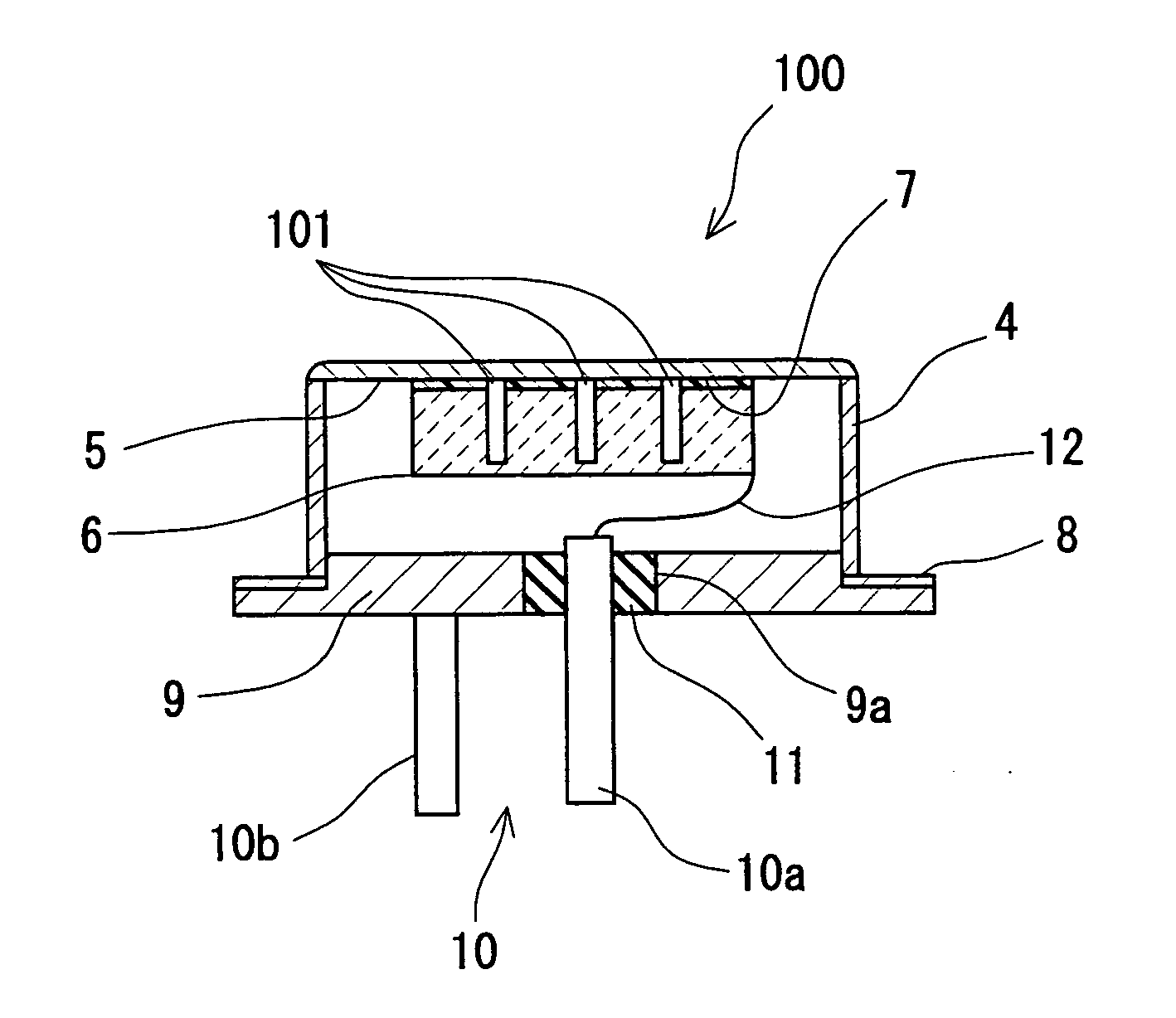
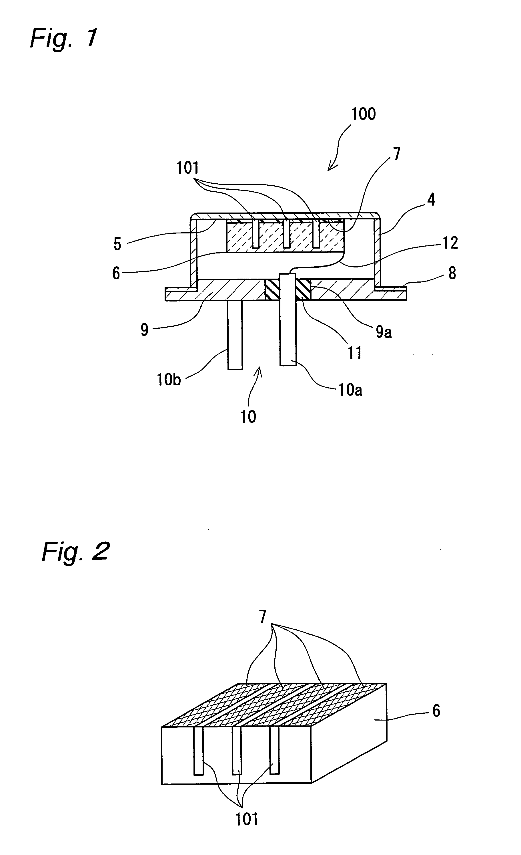
[0067]FIG. 1 shows a sectional view of the ultrasonic vibrator of the first embodiment of the present invention. FIG. 2 is a perspective view of the piezoelectric body of the ultrasonic vibrator of the first embodiment of the present invention.

[0068] In FIGS. 1 and 2, reference numeral 100 denotes an ultrasonic vibrator, 4 a flanged metallic lidded cylindrical casing of one example of the adherend fixation body, 5 an inner wall surface of the ceiling portion of the casing 4, 6 a rectangular parallelepiped piezoelectric body that has electrodes on the mutually opposite surfaces, 7 an adhesive for bonding together the inner wall surface 5 of the ceiling portion of the casing 4 and a surface of the piezoelectric body 6 on which one electrode of the electrodes is formed, 8 a casing support portion of the flange of the casing 4, 9 a terminal plate which is fitted into the opening (open end) of the casing 4 so as to seal the opening of the casing 4 and to which the casing support portion...

second embodiment

[0102]FIG. 14 shows a sectional view of the ultrasonic vibrator of the second embodiment of the present invention.

[0103] In FIG. 14, the reference numeral 120 denotes an acoustic matching layer that establishes acoustic matching with the objective fluid to be measured to increase the efficiency of the ultrasonic vibrator. The other construction is the same as that of the first embodiment.

[0104] The material of the acoustic matching layer 120 is selected according to the objective fluid to be measured, and when the fluid is a liquid, epoxy resin in which various fillers are incorporated, an inorganic material of glass, graphite, or the like can be used. When the fluid is air, a town gas, or the like, the acoustic matching layer 120 can be formed of a composite material in which hollow glass spheres are solidified with a resin based material or an inorganic / organic porous material. The acoustic matching layer 120 is to establish acoustic matching of the objective fluid to be measure...


PUM


Abstract

A difference in the thermal expansion coefficient between a casing and a piezoelectric body is adapted to be reduced by making an adhesive expand and contract, and this can prevent the separation of connection between the casing and the piezoelectric body and the damage of the piezoelectric body. As a result, the ultrasonic vibrator can be used over an extended period of time in an outdoor use environment.

Description

DESCRIPTION [0001] Ultrasonic vibrator and ultrasonic flowmeter employing the same [0002] 1. Technical Field [0003] The present invention relates to an ultrasonic vibrator capable of measuring the flow rate and the flow velocity of a gas or a liquid by means of ultrasonic waves and an ultrasonic flowmeter that employs the vibrator. [0004] 2. Background Art [0005] Conventionally, as an ultrasonic vibrator for use in an ultrasonic flowmeter of the kind, a piezoelectric ceramic 1 has been brazed to a metal diaphragm 2 with a brazing material 3 as shown in FIG. 7 (refer to Japanese Unexamined Patent Publication No. H04-309817 A). DISCLOSURE OF INVENTION [0006] Ultrasonic flowmeters are sometimes used as gas / liquid flow rate monitors of various plants or as domestic gas meters and sometimes installed outdoors in these cases. When an ultrasonic flowmeter is installed outdoors, the device temperature, which is 20° C. to 25° C. before dawn, rises in a short time with sunrise particularly in...

Claims


Application Information

Patent Timeline
Patent Type & Authority Applications(United States)
IPC IPC(8): H01L41/053G01F1/66H04R17/00
CPCH04R17/00G01F1/662
Inventor ADACHI, AKIHISASATO, MASATOHASHIMOTO, MASAHIKO
Owner ADACHI AKIHISA
Why Eureka
Try Eureka