Sound absorbing device for ultra-low frequency sound

a technology of ultra-low frequency sound and absorbent device, which is applied in the direction of gas-turbine engine testing, instruments, transportation and packaging, etc., can solve the problems of scarce data on the sound absorption coefficient of infrasound and the inability to effectively control infrasonic nois

Inactive Publication Date: 2007-01-11
KAWASAKI HEAVY IND LTD
View PDF4 Cites 10 Cited by
  • Summary
  • Abstract
  • Description
  • Claims
  • Application Information

AI Technical Summary

Benefits of technology

[0050] When a jet engine is tested in an engine test cell having a characteristic length of, for example, 80 m contributing to resonance of, for example 80 m, a sound absorbing structure formed by combining a porous layer of 1.6 kg / m2 in surface density with a back air layer of about 4 m in thickness is capable of effectively controlling infrasonic noises generated in the engine test cell.

Problems solved by technology

Data on sound absorption coefficient with infrasounds is scarcely available.
Therefore, if the combination of the porous layer and the air layer is taken for a mass-and-spring dynamic system, it is expected that the air layer must be very thick to absorb infrasounds and such a thick air layer is practically infeasible.

Method used


Image

  • Sound absorbing device for ultra-low frequency sound
  • Sound absorbing device for ultra-low frequency sound
  • Sound absorbing device for ultra-low frequency sound

Examples


first embodiment

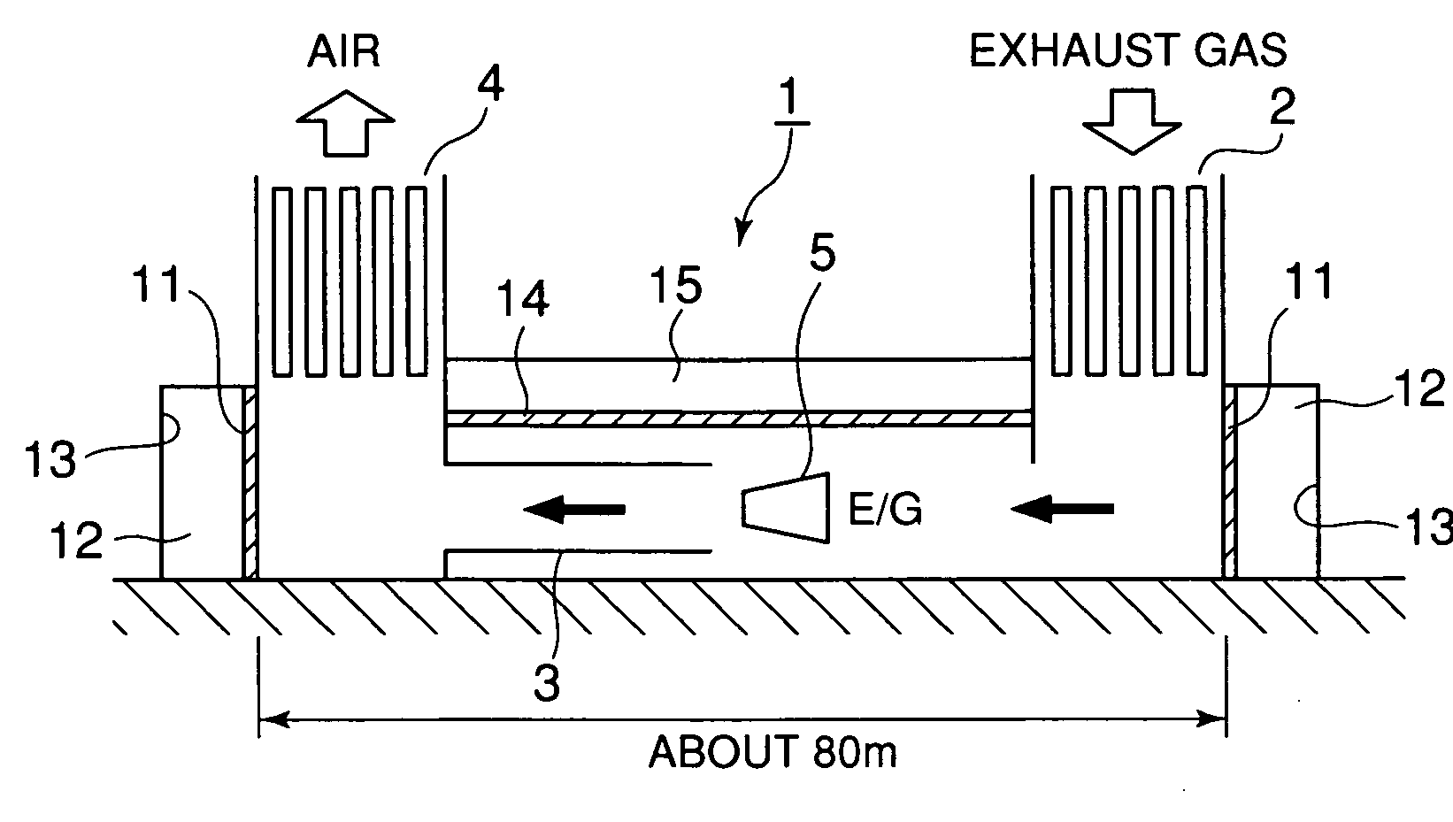
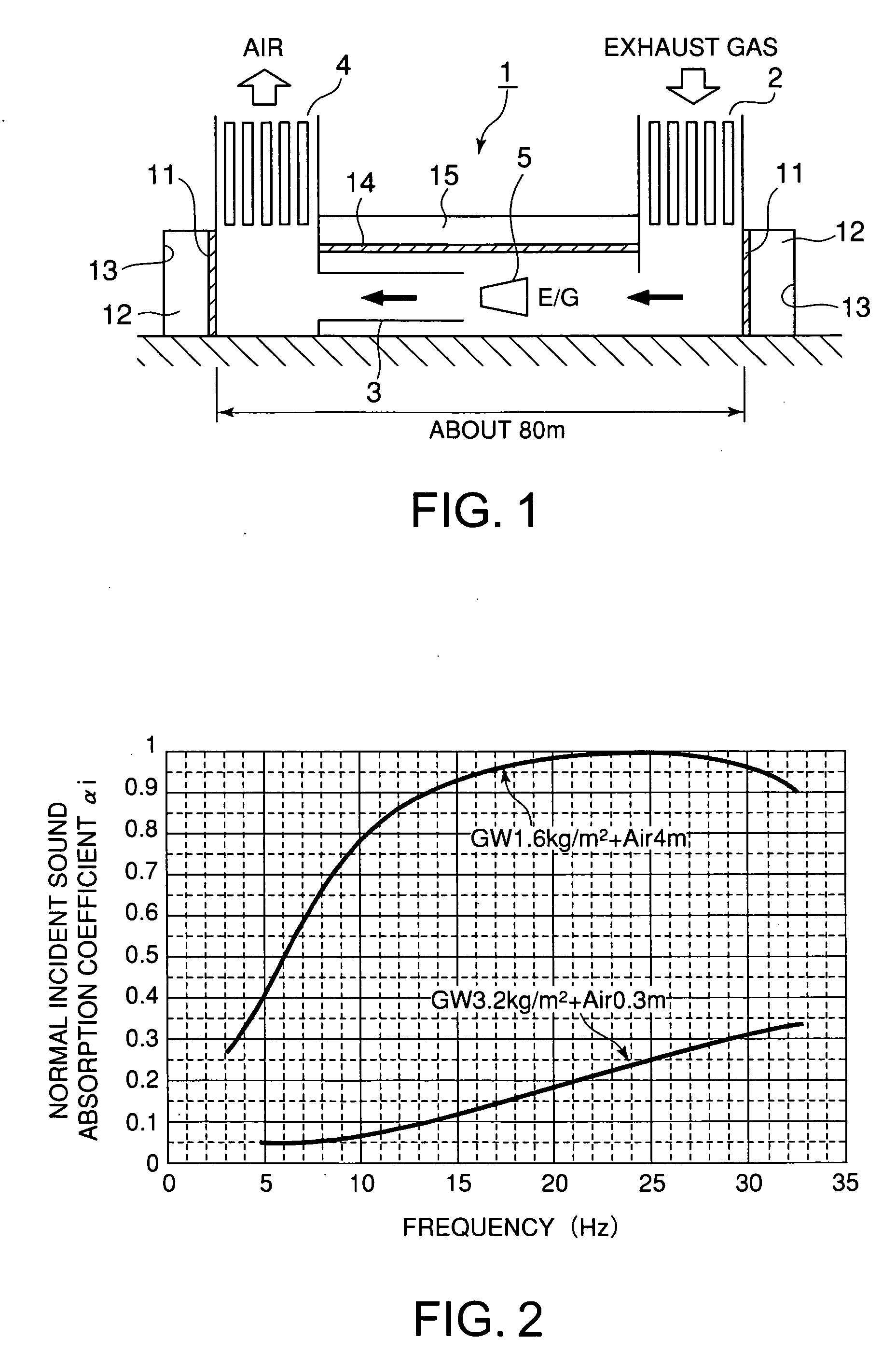
[0066]FIG. 1 is a typical view of a sound absorbing structure in a first embodiment according to the present invention as applied to an engine test cell 1

[0067] The engine test cell 1 defines a chamber of about 80 m in length. The engine test cell 1 is provided with an intake duct 2 at one end thereof and an exhaust duct 4 at the other end thereof. An augmenter 3 for augmenting engine performance is placed in the engine test cell 1 and is connected to the exhaust duct 4. A jet engine 5 is suspended at a position on the upper side of the augmenter 3 for engine performance testing.

[0068] When the jet engine 5 is operated, sound waves of frequencies in a wide frequency range including infrasonic frequencies and high frequencies are generated by the combustion of the fuel, the vibration of the jet engine 5 and air flows on the upper and the lower side of the jet engine 5. Sound energy generated by those sound sources causes the engine test cell 1 to resonate. Consequently, the engine t...

second embodiment

[0101]FIG. 10 is a typical view of a sound absorbing structure in a second embodiment according to the present invention as applied to an engine runup hangar 21. The sound absorption principle of the sound absorbing structure in the second embodiment is entirely the same as the sound absorption principle of the sound absorbing structure in the first embodiment and hence the detail description thereof will be omitted.

[0102] The engine runup hanger 21 defines a long chamber of about 100 m in length. The engine runup hangar 21 is provided with an intake duct 22 at one end thereof and an exhaust duct 24 at the other end thereof. Jet engines of an aircraft 23 are operated in the engine runup hangar 21 for performance tests.

[0103] The operating jet engine generates sound energy having frequencies in a wide frequency range. The sound energy makes the engine runup hangar 21 generate noises of a frequency characteristic peculiar to the engine runup hanger 21. In some cases, the engine runu...


PUM

PropertyMeasurementUnit
thicknessaaaaaaaaaa
thicknessaaaaaaaaaa
frequenciesaaaaaaaaaa

Abstract

An infrasound absorbing structure is simple in construction and is capable of effectively controlling infrasonic noises. The infrasound absorbing structure is applied to an engine test cell or an engine runup hangar to reduce infrasonic noises generate therein. The infrasound absorbing structure includes a porous layer facing an infrasound source, and a back wall disposed opposite to the porous layer so as to define a back air layer of a thickness between 2 and 10 m between the porous layer and the back wall. The porous layer has a surface density in the range of 0.5 to 10 kg/m2.

Description

TECHNICAL FIELD [0001] The present invention relates to a sound absorbent structure capable of absorbing sound waves of frequencies in the infrasonic frequency range and, more particularly, to a sound absorbent structure to be applied to facilities that generates sound waves of frequencies not higher than 20 Hz to absorb infrasounds for environmental protection. BACKGROUND ART [0002] Although infrasonic noises of frequencies between 1 and 20 Hz are inaudible, such infrasonic noises having long wavelengths propagate to distant places and cause not only physical problems including rattling of fittings but also psychological problems including nausea and irritation and physiological problems including headache and insomnia. [0003] For example, there are many machines which can be sources of infrasonic noises, such as machines installed in plants and vibration screens used to sort rock and aggregate dug from the ground by subway construction work, even in urban areas. [0004] Jet streams...

Claims


Application Information

Patent Timeline
Patent Type & Authority Applications(United States)
IPC IPC(8): B32B3/26E04B1/82B64F1/26G01M9/00G01M15/00G01M15/14G10K11/16G10K11/172
CPCB64F1/26G10K11/172G01M9/00Y10T428/249953
Inventor AOKI, MAKOTOODA, MITSUAKISATOMI, TAKAYUKI
Owner KAWASAKI HEAVY IND LTD
Why Eureka
Try Eureka