Antenna matching apparatus

a technology for matching apparatuses and antennas, applied in the direction of antenna details, electrically long antennas, antennas, etc., can solve the problems of increasing power loss and impedance mismatching, and achieve the effect of reducing power loss and removing impedance mismatching

Inactive Publication Date: 2007-01-11
PANASONIC CORP
View PDF3 Cites 43 Cited by
  • Summary
  • Abstract
  • Description
  • Claims
  • Application Information

AI Technical Summary

Benefits of technology

[0008] According to the present invention, it is possible to eliminate impedance mismatching produced when an antenna apparatus mount

Problems solved by technology

In this state, the input impedance of helical antenna 12 varies dr

Method used


Image

  • Antenna matching apparatus
  • Antenna matching apparatus
  • Antenna matching apparatus

Examples


embodiment 1

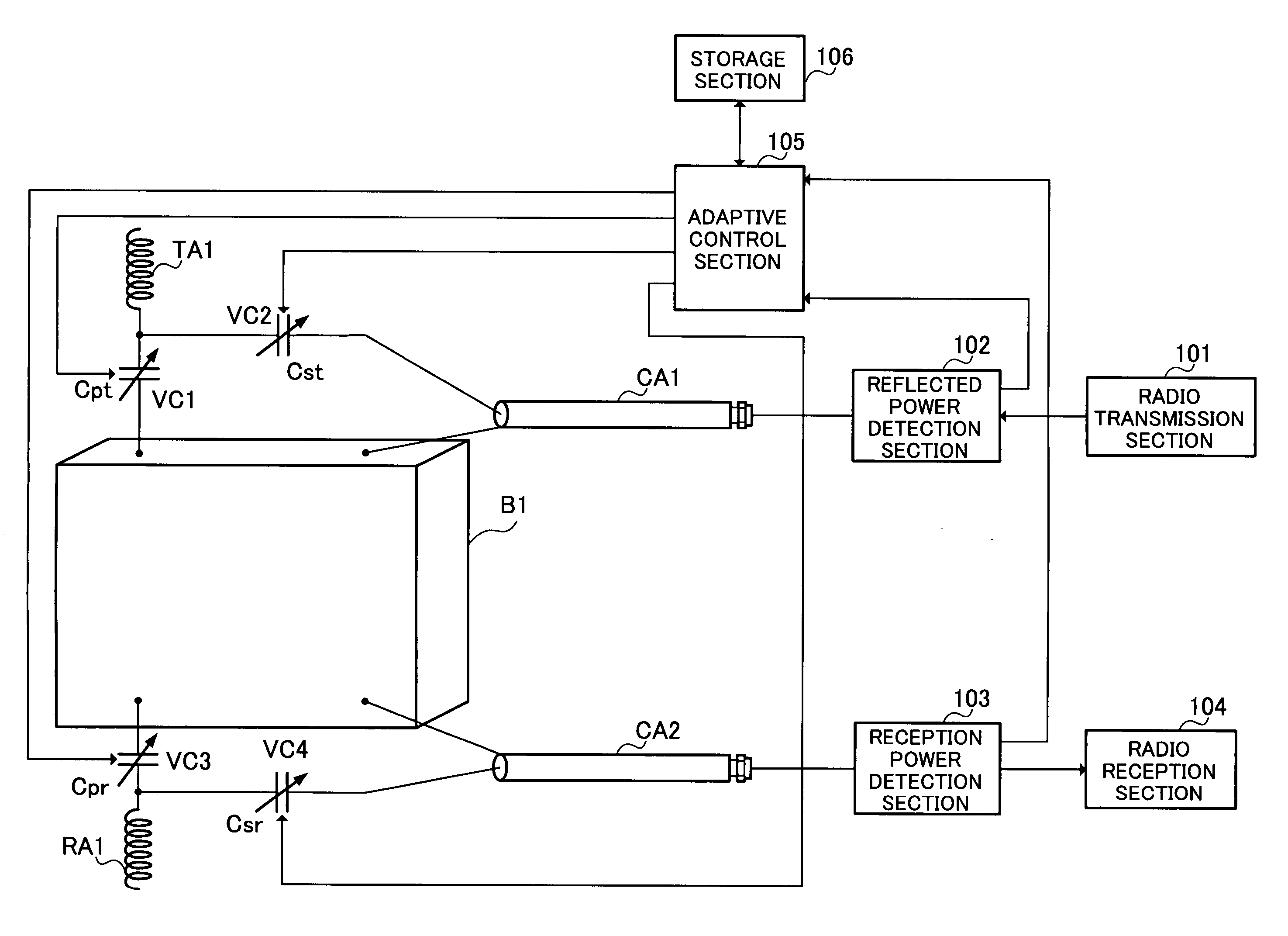
[0022]FIG. 3 is a block diagram showing the configuration of an antenna matching apparatus according to Embodiment 1 of the present invention. In this figure, one end of transmission antenna element TA1 is connected to radio set case B1 made of a conductor via variable capacitance capacitor VC1 and also connected to a central conductor of a coaxial cable CA1 which is an unbalanced feeding line via variable capacitance capacitor VC2.

[0023] One end of reception antenna element RA1 is connected to radio set case B1 via variable capacitance capacitor VC3 and also connected to a central conductor of coaxial cable CA2 via variable capacitance capacitor VC4. Grounding conductors of coaxial cables CA1 and CA2 are connected to radio set case B1. Furthermore, the central conductor of coaxial cable CA1 is connected to reflected power detection section 102 and the central conductor of coaxial cable CA2 is connected to reception power detection section 103. Note that variable capacitance capaci...

embodiment 2

[0054] Embodiment 1 explains the case where impedance matching is realized by controlling capacitance values of variable capacitance capacitors. This embodiment will explain a case where impedance matching is realized by controlling a voltage applied to a variable capacitance diode.

[0055]FIG. 8 is a block diagram showing the configuration of an antenna matching apparatus according to Embodiment 2 of the present invention. However, portions in FIG. 8 common to the parts in FIG. 3 are assigned the same reference numerals as those in FIG. 3 and detailed explanations thereof will be omitted.

[0056] One end of transmission antenna element TA1 is connected to a cathode of variable capacitance diode VD1 at connection point P1 and an anode of variable capacitance diode VD1 is connected to radio set case B1 via high-frequency prevention inductor L1 connected to connection point P31.

[0057] Furthermore, the one end of transmission antenna element TA1 is connected to high-frequency prevention...

embodiment 3

[0070]FIG. 9 is a block diagram showing the configuration of an antenna matching apparatus according to Embodiment 3 of the present invention. However, portions in FIG. 9 common to those in FIG. 3 are assigned the same reference numerals and detailed explanations thereof will be omitted.

[0071] One end of transmission antenna element TA1a is connected to radio set case B1 made of a conductor via variable capacitance capacitor VC1a and also connected to a central conductor of coaxial cable CA1a which is an unbalanced feeding line via variable capacitance capacitor VC2a. A grounding conductor of coaxial cable CA1a is connected to radio set case B1. Furthermore, the central conductor of coaxial cable CA1a is connected to reflected power detection section 102a.

[0072] One end of reception antenna element RA1a is connected to radio set case B1 made of a conductor via variable capacitance capacitor VC3a and also connected to a central conductor of coaxial cable CA2a which is an unbalanced...


PUM


Abstract

An antenna matching apparatus capable of eliminating impedance mismatching produced when the antenna element is placed close to the human body in a short time and reducing power loss due to impedance mismatching. This apparatus connects variable capacitance capacitors VC1 and VC2 for impedance adjustment to transmission antenna element TA1, connects variable capacitance capacitors VC3 and VC4 to reception antenna element RA1 respectively, provides beforehand capacitance values of respective variable capacitance capacitors which are impedance matched in a table in a one-to-one correspondence with the distances between the antenna elements and human body and stores the table in storage section (106). The apparatus completes adaptive control processing for any one of transmission antenna element TA1 and reception antenna element RA1, reads other capacitance values corresponding to the capacitance value at that moment from the table and performs adaptive control processing on other antenna elements using the read values as initial values.

Description

TECHNICAL FIELD [0001] The present invention relates to an antenna matching apparatus suitable for use in, for example, a radio communication apparatus such as a cellular phone set. BACKGROUND ART [0002]FIG. 1 illustrates the configuration of a conventional cellular phone set. In this figure, case 11 is provided with helical antenna 12 outside the case and helical antenna 12 is connected to matching circuit 13 inside the case. [0003] Furthermore, inside the case, matching circuit 13 is connected to radio transmission section 15 and radio reception section 16 via changeover switch 14. Matching circuit 13 is normally adjusted so that input impedance of helical antenna 12 is matched at an operating frequency in a free space. [0004]FIG. 2 illustrates an example of a cellular phone set shown in FIG. 1 when placed close to a human body. Here, the phone set is in a communication state as it is placed close to the human body. In this state, the input impedance of helical antenna 12 varies d...

Claims


Application Information

Patent Timeline
IPC IPC(8): H04B1/04H01Q1/24H04B1/18H04B1/3822H04B1/40
CPCH01Q1/245H04B1/18H04B1/0458
Inventor TAKAHASHI, TSUKASAKOYANAGI, YOSHIOOGAWA, KOICHI
Owner PANASONIC CORP
Why Eureka
Try Eureka