Part feeder

a feeder and part technology, applied in the direction of stacking articles, instruments, de-stacking articles, etc., can solve the problems of disadvantageously affecting production efficiency, achieve compact structure, reduce or minimize swaying motion, and avoid the effect of disadvantageous upsizing of the part feeder in its entirety

Inactive Publication Date: 2007-01-18
HONDA MOTOR CO LTD
View PDF15 Cites 9 Cited by
  • Summary
  • Abstract
  • Description
  • Claims
  • Application Information

AI Technical Summary

Benefits of technology

[0010] In this arrangement, the plurality of parts may be brought together at the distal end of the rod with no clearance left between adjacent parts, and thus the totalized thickness of the plurality of parts can be measured by the measuring device with accuracy. In addition, an outer cylindrical surface of the rod, especially an upper side thereof, may preferably be formed with a smooth surface free of irregularities so that the plurality of parts may smoothly slide toward the distal end of the rod by centrifugal force.
[0011] In another exemplary embodiment, additionally or alternatively, the holding device may include a detection unit adapted to detect a part placed in the standby position. Provision of such a detection unit in the holding device makes it possible to prevent failure to feed any part remaining in the standby position. The detection unit may be integrally provided in the holding device, so that disadvantageous upsizing of the part feeder in its entirety can be avoided and a compact structure can be achieved.
[0012] In yet another exemplary embodiment, additionally or alternatively, the holding device may include an antisway mechanism adapted to come in close proximity to the at least one part held in suspension with the rod inserted through the through hole of the at least one part in order to prevent the at least one part from swaying. Provision of such an antisway mechanism in the holding device serves to reduce or minimize the swaying motion of the at least one part held in suspension. Accordingly, the measuring device can start measuring the thickness of the at least one part irrespective of the swaying motion of the at least one part (without the need for waiting until the at least one part stops swaying), so that the time required for measurement can be reduced. Since the antisway mechanism is adapted to come in close proximity to the at least one part, the antisway mechanism may be designed so as not to press against the at least one part. In this embodiment, the at least one ...

Problems solved by technology

The above setup as is typically the case with conventional part feeders would allow an irregular part different in thickness from regular parts, which could be included in the parts placed in the standby position, to be fed...

Method used


Image

  • Part feeder
  • Part feeder
  • Part feeder

Examples


Embodiment Construction

[0027] A detailed description of exemplary embodiments of the present invention will be given with reference made to the drawings where appropriate.

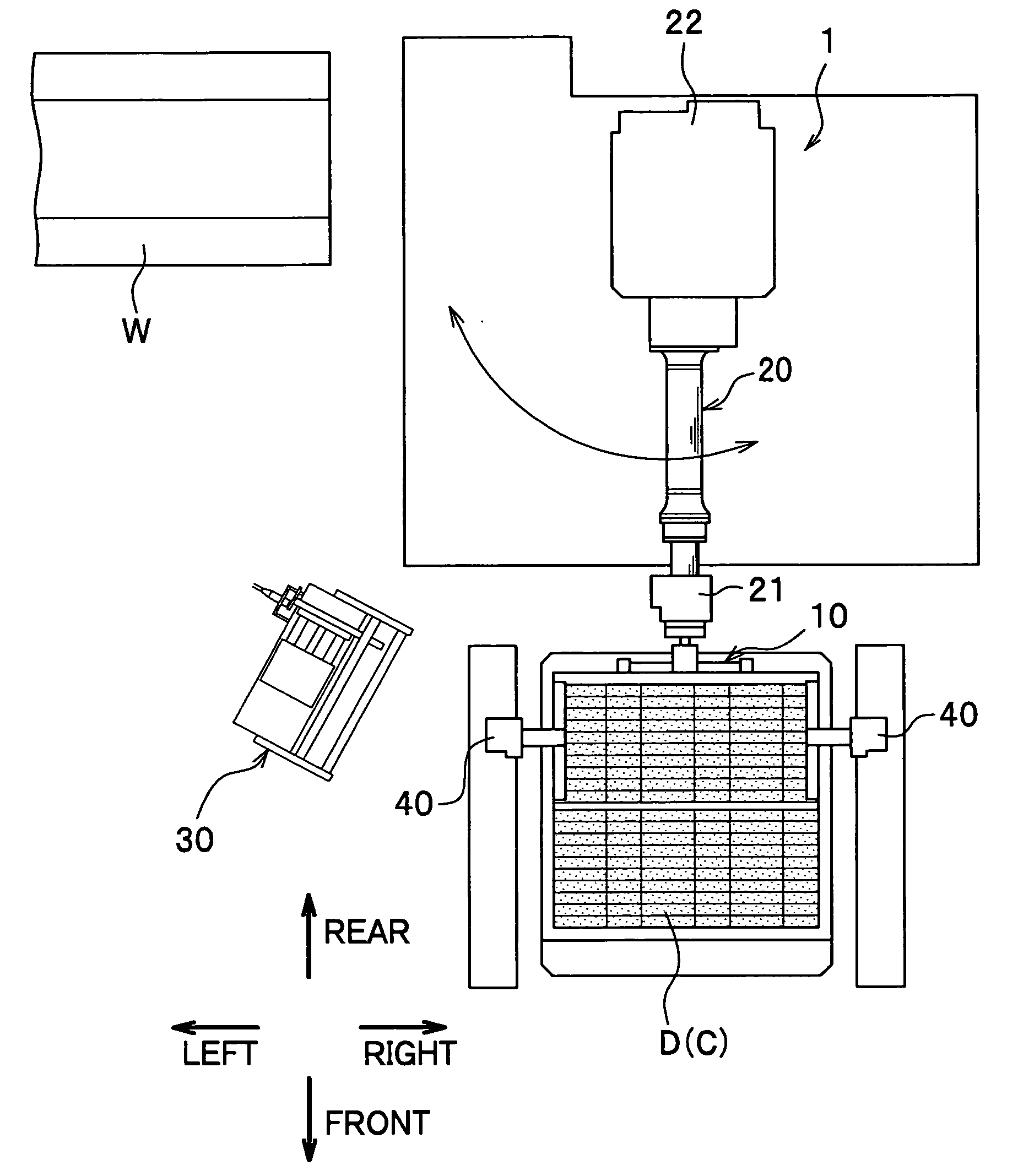
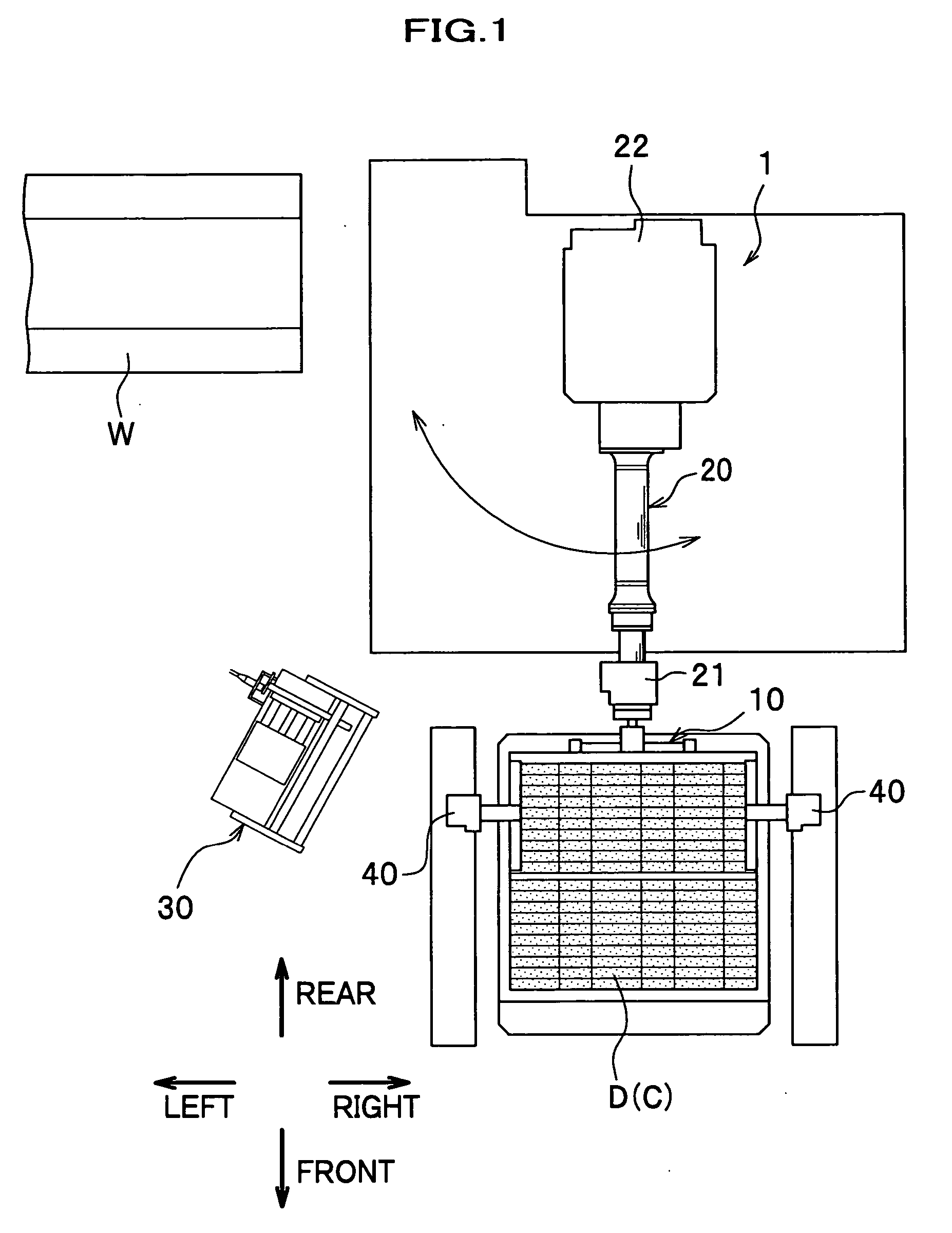
[0028] In the following description, a part feeder consistent with the present invention is exemplified by a part feeder 1 as shown in FIG. 1 for feeding connecting rods C placed in a dunnage D (standby position) to a walking beam W (a conveyor provided in a predetermined position). Connecting rod C is, as shown in FIGS. 4A and 4B, a long member for use in an automotive engine or the like. The connecting rod C has a big end in which a through hole C2 is provided.

[Part Feeder]

[0029] The part feeder 1 includes a holding device 10, a robot arm 20 and a measuring device 30, as shown in FIG. 1. The holding device 10 holds a plurality of connecting rods C placed in the dunnage D. The robot arm 20 is a transport mechanism adapted to move the holding device 10 to a predetermined position. The measuring device 30 is adapted to measure a totali...


PUM

PropertyMeasurementUnit
Fractionaaaaaaaaaa
Thicknessaaaaaaaaaa

Abstract

A part feeder for feeding at least one part having a through hole from a standby position to a predetermined position includes a holding device, a transport mechanism, and a measuring device. The holding device has a rod disposed in a horizontal position. The holding device is adapted to hold the at least one part in suspension with the rod inserted through the through hole of the at least one part. The transport mechanism is adapted to move the holding device holding the at least one part in suspension from the standby position to the predetermined position. The measuring device is adapted to measure a thickness of the at least one part held by the holding device.

Description

CROSS-REFERENCE TO RELATED APPLICATION(S) [0001] This application claims the foreign priority benefit under Title 35, United States Code, §119 (a)-(d), of Japanese Patent Application No. 2005-206858 filed on Jul. 15, 2005 in the Japan Patent Office, the disclosure of which is herein incorporated by reference in its entirety. BACKGROUND OF THE INVENTION [0002] This invention relates to a part feeder for feeding a part having a through hole from a standby position to a predetermined position. [0003] A variety of part feeders for feeding at least one part having a through hole from a standby position to a predetermined position have been proposed. For example, disclosed in JP 8-1568 A (see Paragraphs 0020-0021; FIGS. 1 and 6) is a part feeder which includes a holding device and a robot. The holding device illustrated therein has a rod disposed in a horizontal position, and is adapted to carry a plurality of discs with the rod inserted through the center holes of the discs so that the d...

Claims


Application Information

Patent Timeline
IPC IPC(8): A01K61/02B65H5/00B21F45/18
CPCY10T29/49782B65G61/00
Inventor HANAOKA, TADASHIMARUYAMA, SHUICHIHIGUMA, TOSHIROU
Owner HONDA MOTOR CO LTD
Why Eureka
Try Eureka