
Braking system for vehicle and braking method thereof

a technology for braking systems and vehicles, applied in braking systems, vehicle position/course/altitude control, instruments, etc., can solve the problems of complex structure, high cost, and operator's unusual pedal feeling, and achieve the effect of simple configuration, low cost and high reliability

Inactive Publication Date: 2007-01-18
HL MANDO CORP
View PDF9 Cites 52 Cited by
  • Summary
  • Abstract
  • Description
  • Claims
  • Application Information

AI Technical Summary

Benefits of technology

[0010] The present invention has been made in order to solve the above problems. It is an aspect of the invention to provide a braking system for vehicles, which can achieve simplified configuration, low costs, and high reliability while maintaining a constant pedal pressure despite the alteration of a brake hydraulic pressure by a regenerative braking force, and a braking method thereof.

Problems solved by technology

However, in the case where such a decrease in brake hydraulic pressure is realized by brake oil in a master cylinder, there is a problem in that a brake pedal is depressed unintentionally due to a decreased pressure, thereby providing the vehicle operator with unusual pedal feeling.
Although an electro-hydraulic brake (EHB) may be used to keep a braking pressure and pedal pressure constant, the EHB has problems of complicated structure and high costs thereof, and suffers from deterioration in braking reliability / durability.

Method used


Image

  • Braking system for vehicle and braking method thereof
  • Braking system for vehicle and braking method thereof
  • Braking system for vehicle and braking method thereof

Examples


Embodiment Construction

[0025] Reference will now be made in detail to exemplary embodiments of the present invention, examples of which are illustrated in the accompanying drawings, wherein like reference numerals refer to like elements throughout. The embodiments are described below to explain a pump assembly for a brake system consistent with the present invention by referring to the figures.

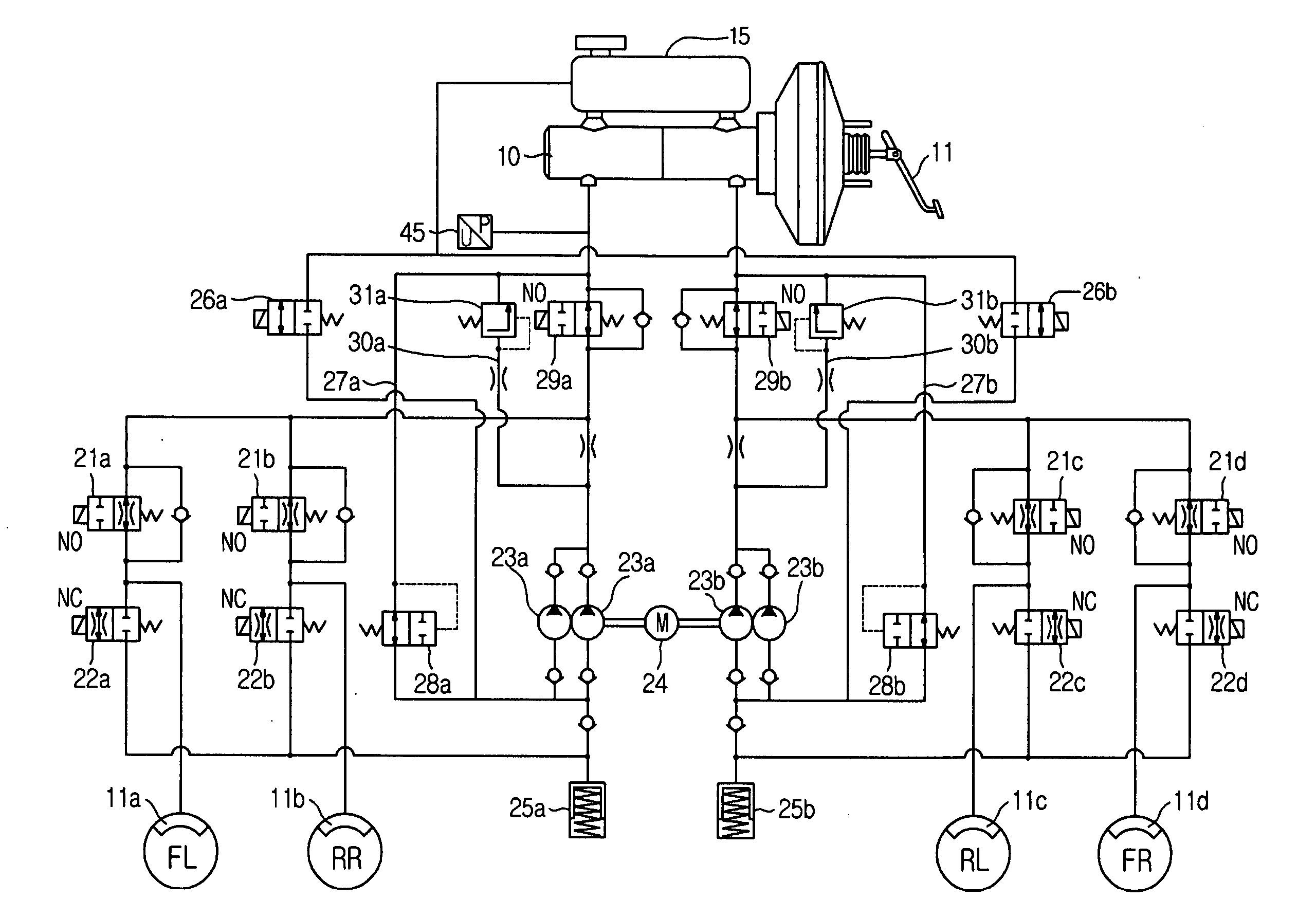
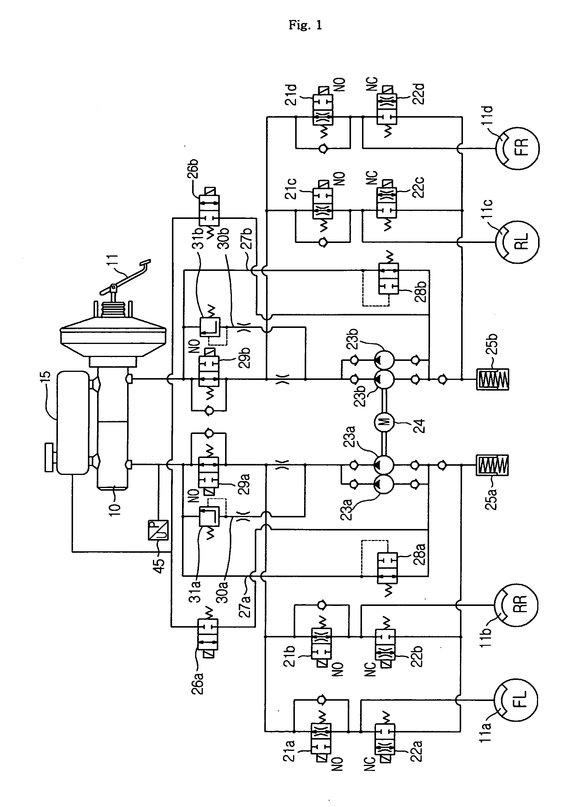
[0026]FIG. 1 is a hydraulic circuit diagram of a braking system consistent with the present invention. In operation of the braking system, if a vehicle operator's pedal toe force is applied to a booster through a brake pedal 11, the pedal toe force is increased by the booster and transmitted to a master cylinder 10. Thereby, a hydraulic pressure is generated in the master cylinder 10 and is transmitted to respective wheel cylinders 11a to 11d through first and second traction control valves 29a and 29b and first electronic valves 21a to 21d, which are normal open type valves. Also, to achieve the return of brake oi...


PUM


Abstract

A braking system for a vehicle, which can prevent an alteration in brake pedal toe force when a brake hydraulic pressure is increased or decreased based on a regenerative braking force obtained by a drive motor in an electric vehicle or hybrid vehicle, and a braking method thereof. To prevent an alteration in brake pedal toe force, the vehicle braking system includes a brake reservoir to receive brake oil therein, a normal close type valve to connect the brake reservoir to an inlet of a pump generating a hydraulic pressure in a brake line, a drive motor serving as a generator, the drive motor being adapted to convert a kinetic energy of the vehicle into electric energy to brake the vehicle by regenerative braking, and a control unit to recognize the amount of regenerative braking obtained by the drive motor and the amount of braking desired by a vehicle operator and to control the normal close type valve, so as to compensate for a brake hydraulic pressure corresponding to a difference between the regenerative braking amount and the desired braking amount by use of the brake oil in the reservoir.

Description

CROSS-REFERENCE TO RELATED APPLICATION [0001] This application claims the benefit of Korean Patent Application No. 2005-0118468, filed on Dec. 7, 2005 in the Korean Intellectual Property Office, the disclosure of which is incorporated herein by reference. BACKGROUND OF THE INVENTION [0002] 1. Field of the Invention [0003] The present invention relates to a braking system for a vehicle, and, more particularly, to a braking system for a vehicle, which can prevent an alteration in brake pedal toe force when a brake hydraulic pressure is increased or decreased based on a regenerative braking force obtained by a drive motor in an electric vehicle or hybrid vehicle, and a braking method thereof. [0004] 2. Description of the Related Art [0005] Generally, in operation of a braking system, if a vehicle operator presses a brake pedal, a pressure corresponding to a boost ratio of a booster is generated in a master cylinder based on a pedal toe force applied by the vehicle operator. As the pres...

Claims


Application Information

Patent Timeline
IPC IPC(8): B60T8/64
CPCB60L7/26B60T1/10B60T2270/602B60T8/4059B60T8/4872B60T8/00B60L7/10
Inventor YANG, I-JIN
Owner HL MANDO CORP
Features
  • Generate Ideas
  • Intellectual Property
  • Life Sciences
  • Materials
  • Tech Scout
  • Unparalleled Data Quality
  • Higher Quality Content
  • 60% Fewer Hallucinations
Learn More